Some of the first posts on this blog were about how to interact with the famous nRF24L01 2.4GHz radio chipset from both an Arduino and a Raspberry Pi. Well.. Much have happened in the mean time, but at least I have managed to put together something using what I learned back then. I decided to make a wireless monitoring system for environmental data in and around our house with at least one sensor node in each room as well as a couple of sensors outside. It is called RPIWeather and you can get all the code and documentation by clicking the name. This post is just meant as a short summary.
RPIWeather consists of a bunch of wireless sensor nodes, a base station that collects the data packets, a database server, and one or more frontends. My goal has been to collect data at 5 minute intervals and keep it indefinitely for analysis, comparison, and visualization. This creates some demands for power efficiency and reliability, which I find interesting.
The sensor nodes
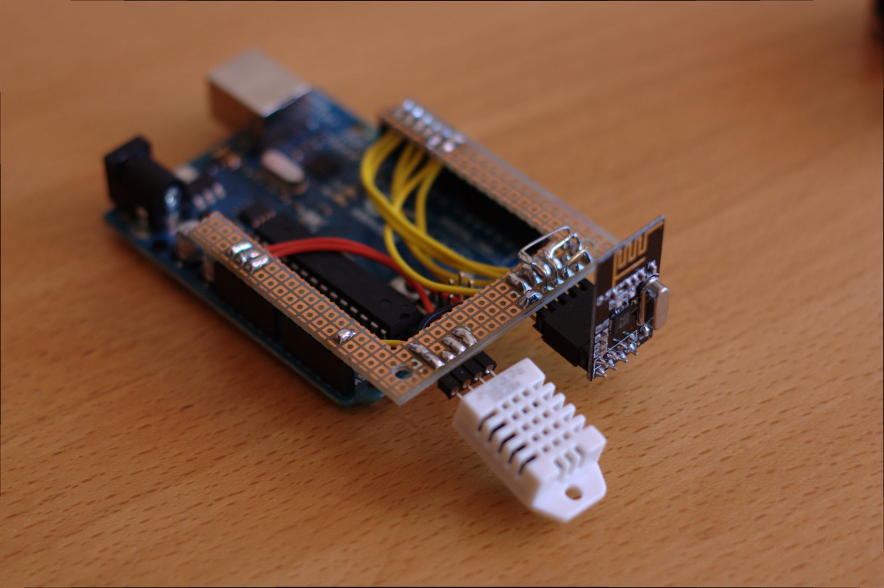
My first prototype was based around an Arduino and some proto-board and is described here, here, and here. It looked like this:
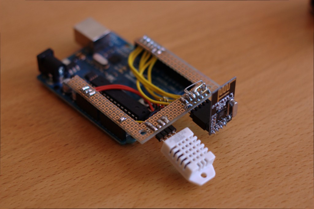
Arduino with nRF24L01 and DHT22
To keep things simple, clean, and small, I decided to ditch the Arduino platform and code in straight avr-libc for the ATtiny84 chip from Atmel. So I made another prototype, but this time with an ATtiny84 instead.
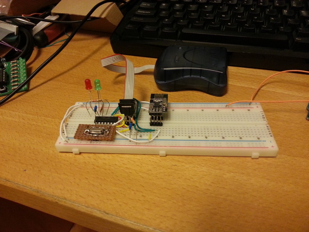
Partial prototype without the DHT22 sensor
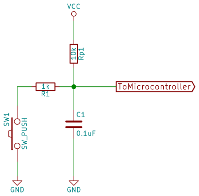
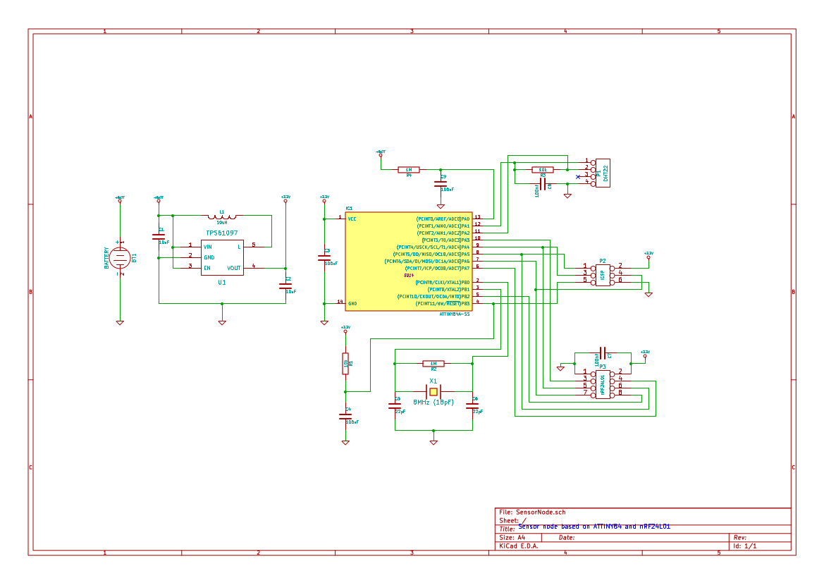
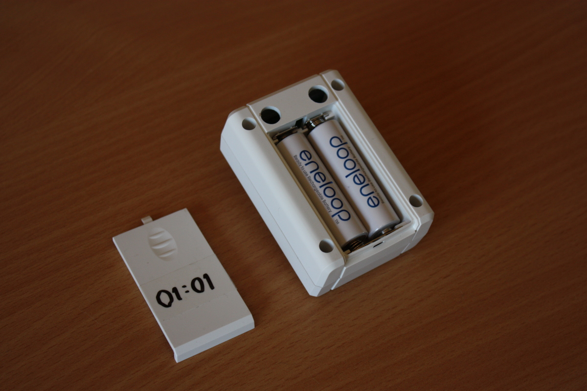
Little by little a schematic emerged. Besides the radio, the sensor and the MCU, I also needed some sort of power supply. As the sensor nodes are to be distributed throughout the house, this implied battery power, but it couldn’t just be any old battery. The thing is that the radio chip can only tolerate up to 3.6v and the DHT22 sensor can only operate down to ~3v, which leaves a narrow band of usable voltages. A traditional voltage regulator would have burned though the batteries quite quickly, so I had to put in a switching boost converter. This way 2 AA NiMH batteries can deliver a reasonably stable 3.3v supply voltage for the circuit. Pro tip: when buying NiMH batteries, do yourself a favor and use the low self-discharge kind like Eneloop. In this use-case they will go for several months between charges.
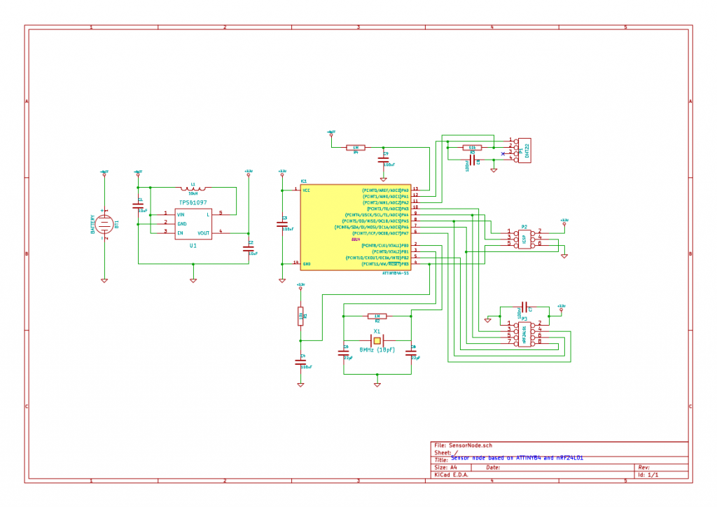
Schematic for the sensor nodes
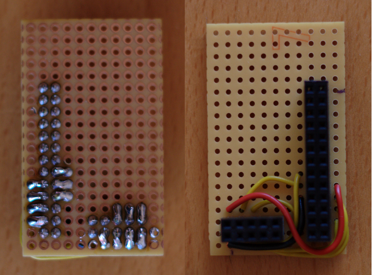
With the schematic in place, I made a PCB layout and sent it to ITEAD for manufacturing. Here are a couple of pictures showing various stages of assembly. The funny shape of the boards was needed to make them fit snugly into some cool boxes from New Age Enclosures.
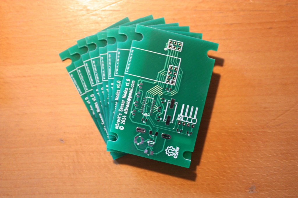
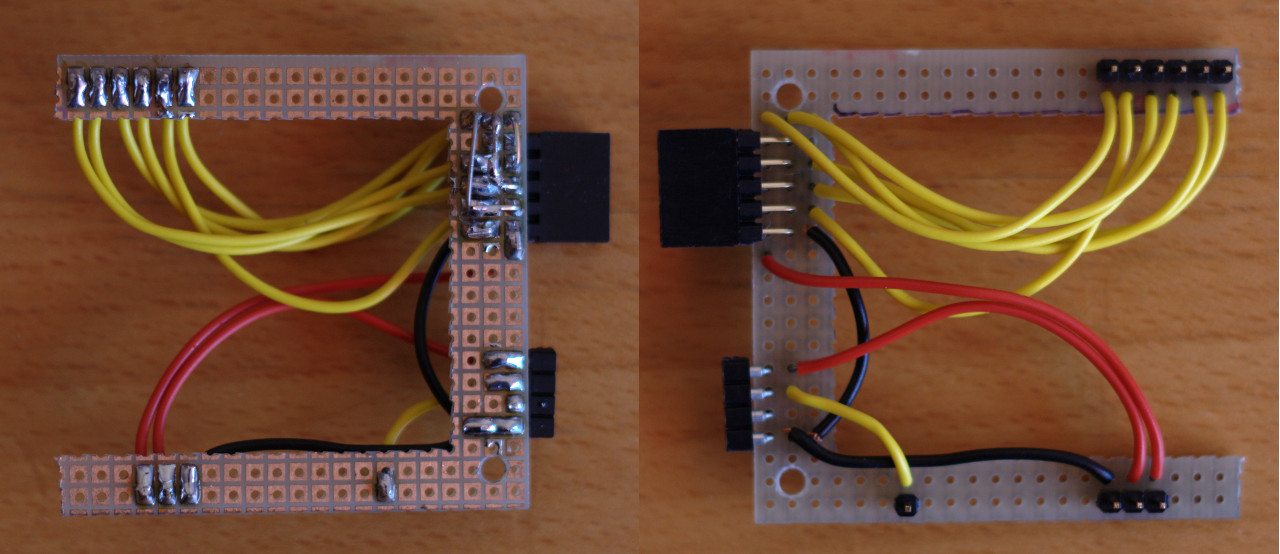
Sensor node PCBs
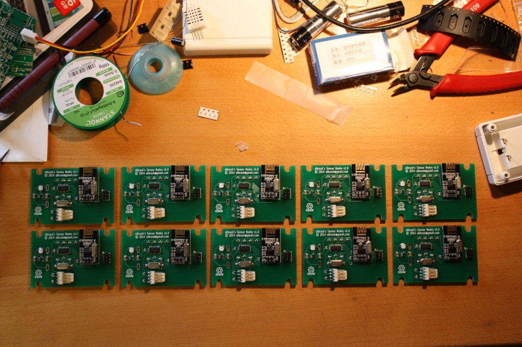
The first 10 finished boards
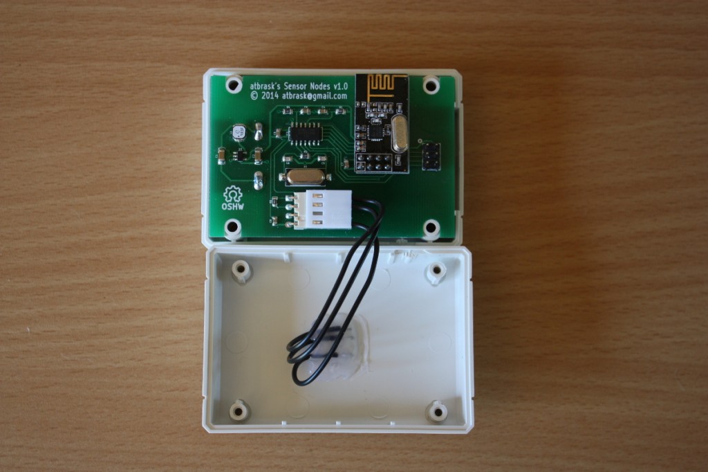
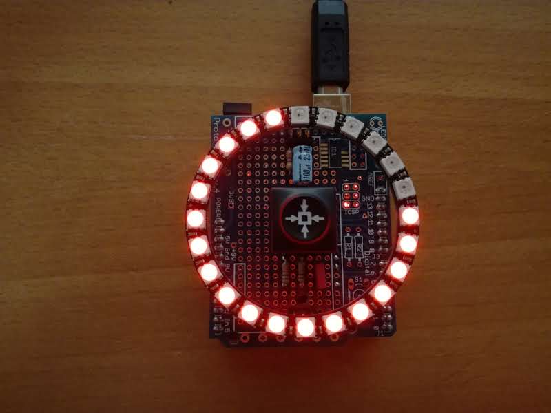
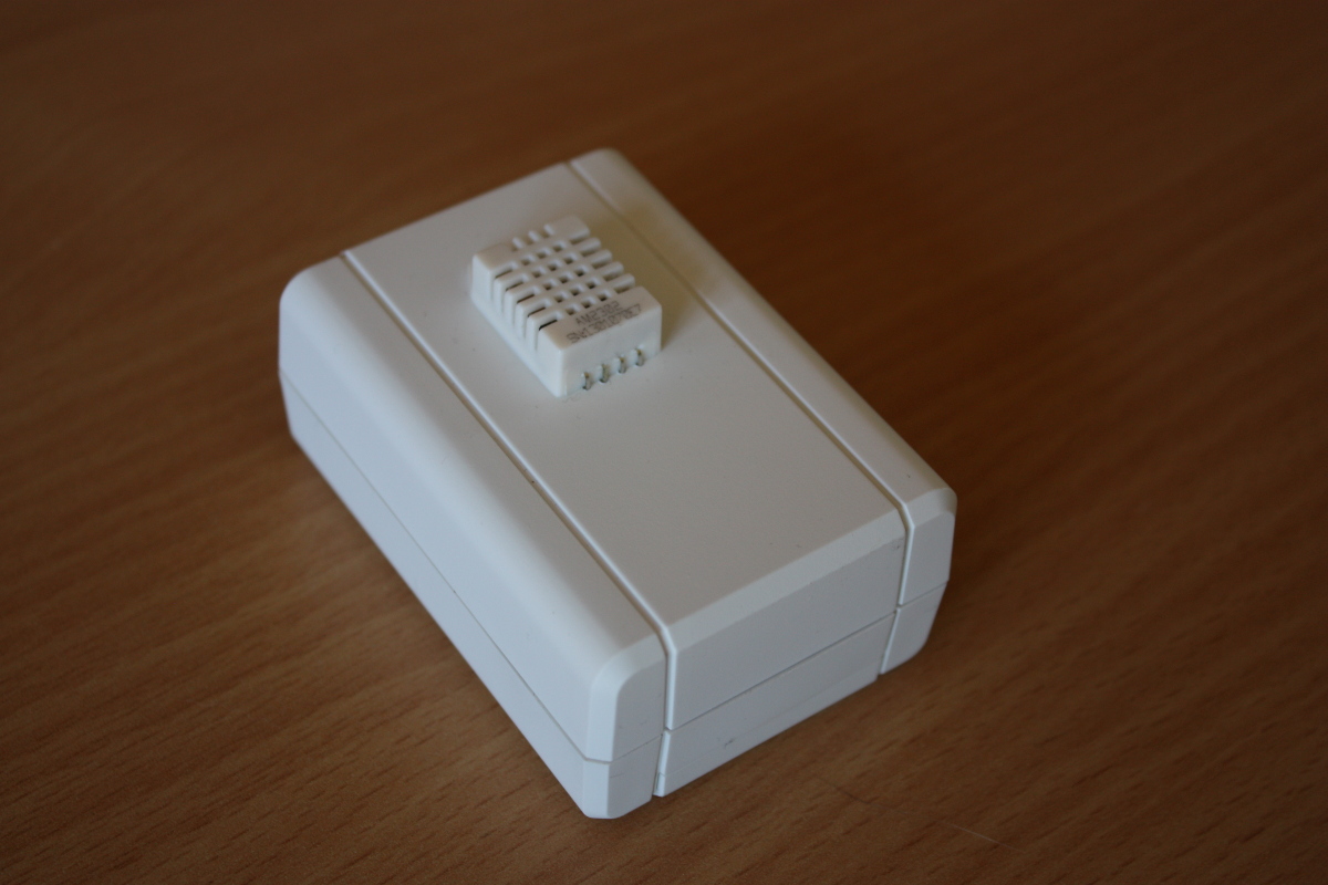
Inside a single sensor node

A single sensor node
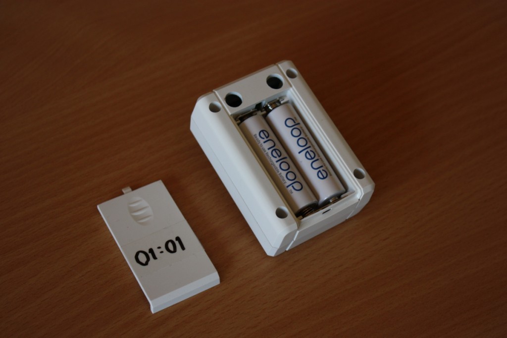
The back of a sensor node
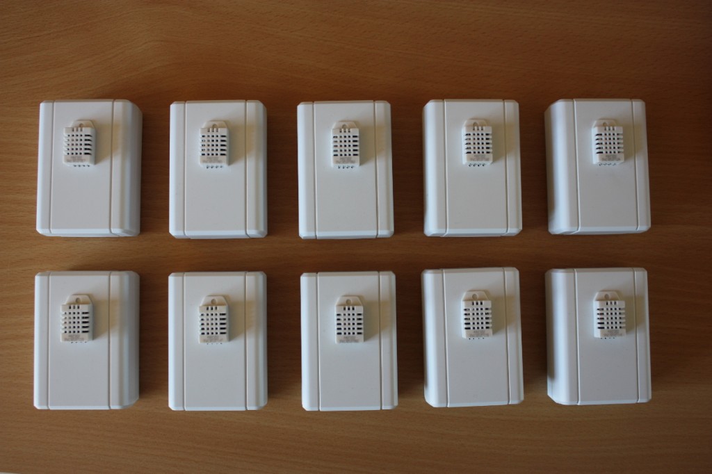
The 10 first sensor nodes
In addition to the DHT22 sensors, I have also made firmware for collecting data from a wind vane and a rain gauge. But I haven’t deployed any of that yet. Maybe next spring…
All in all the main results for the sensors are:
- They work! I have tested concurrent operation of 10 units without major problems.
- Firmware optimized for ATtiny84 @ 1 MHz (8MHz crystal with the CKDV8 fuse set)
- Temperature and humidity measurement using a DHT22 sensor
- Wind speed and wind direction measurement using a La Crosse TX23 anemometer
- Rainfall measurement using a WS-2300-16 rain gauge
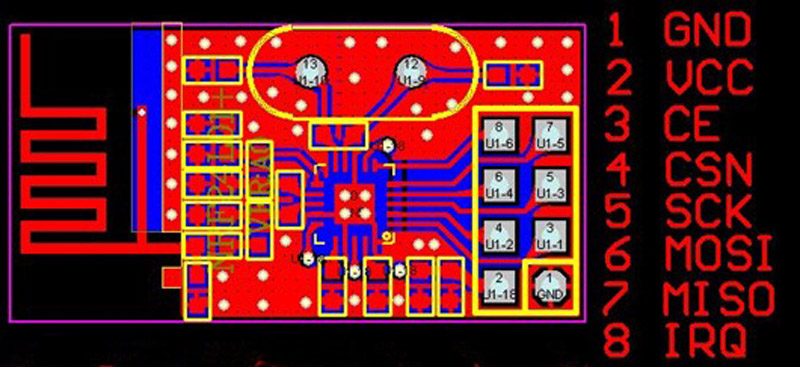
- Wireless operation using the very popular nRF24L01+ 2.4 GHz radio chip
- Very compact CRC32 implementation
- Battery powered operation using a very efficient 3.3v DC/DC converter
- Power management by sleeping the CPU and turning off unneeded hardware
- Battery voltage measurement included in data packet
- Typical battery draw while sleeping has been measured to around 17uA
- Total firmware size from 3.0 kiB to 3.5 kiB (depending on sensor type)
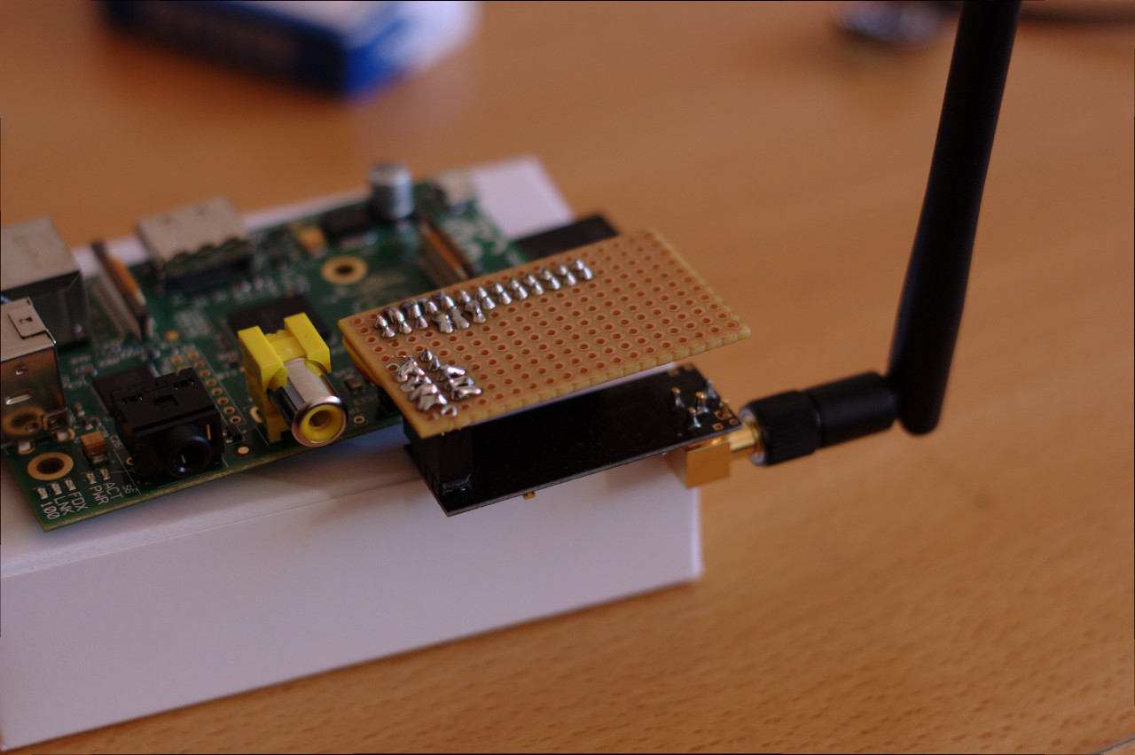
The base station
I use a Raspberry Pi as base station. To make it more appliance-like than a typical Raspbian installation, I have instead installed a variant of Tiny Core Linux called piCore. This is basically a very small Linux distribution that loads all programs into memory on boot and leaves the SD card alone after this. This eliminates the usual risk of corrupting the file system when doing a power-cycle.
On the base station I have installed a small python script that continually polls the nRF24L01 radio using the Raspberry Pi’s built-in SPI interface pins. When a data packet arrives, it is buffered (in case of network problems) and forwarded to the database.
The database
With my limited data requirements, I could probably use any old database out there without issues. However, given the nature of the data, it was natural to select a so-called timeseries database. For this project I chose InfluxDB, which was very, very easy to set up on my Ubuntu-based file server. It automatically exposes a simple HTTP interface for storing and querying data, which is just what I need for this project.
The frontend(s)
Well, I’m not quite there yet… So far the only frontend is the admin interface that is built in to InfluxDB. Not very user friendly (not to mention the Wife Acceptance Factor)! The next step now is to make some sort of nice frontend for this. I have several ideas floating around my head:
- An intranet website. The easiest way.
- An Android widget. Both the wife and I have Android smartphones.
- Dedicated hardware devices. This would be a great use-case for my new ESP8266 wifi modules and some 84×48 Nokia LCDs I have lying around.
Stay tuned…