So, the last couple of years I have been developing and using my own home-built wireless thermometer/hygrometer system called RPIWeather (which is open source). Then the other day I discovered that the previous owners of our house (my in-laws) had left a few items outside. To be more precise, they left a couple of wireless thermometer sensors from old weather stations. The weather stations are long gone by now and, needless to say, the batteries were quite dead. But that doesn’t mean the devices themselves don’t work. Hmm.. It might even be possible to add these into my own system. I always like a good challenge…
Let’s have a look…
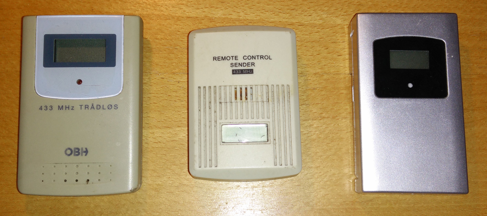
Three wireless thermometers
The devices all looked a bit gnarly, but after a bit of clean-up I powered them on one by one and had a look using my RTL-SDR receiver. All three devices worked and transmitted on 433MHz. Yay! But as my RPIWeather base station only supported the nRF24L01 2.4GHz transceivers, I had to make and add a new 433MHz receiver to it.
Setting up a prototype receiver
At first I toyed with the idea of simply adding an RTL USB-dongle to my Raspberry Pi and simply use GNU Radio (or some other SDR framework) to receive the signals. But that seemed a bit overkill. And I’m not even sure a first generation Raspberry Pi is powerful enough for this to work properly. Fortunately, the usual Chinese Ebay sellers offer a few different generic 433MHZ ASK/OOK receiver modules.
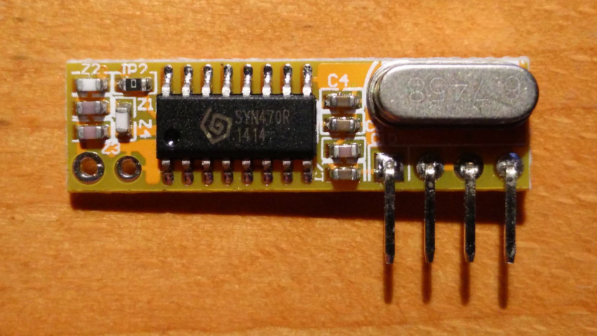
RXB12
I ended up choosing one called RXB12 which features a Synoxo SYN470R IC. It’s reasonably sensitive across the 433MHz spectrum, but doesn’t offer any I/O besides a continuous stream of binary data (which is just random noise most of the time).
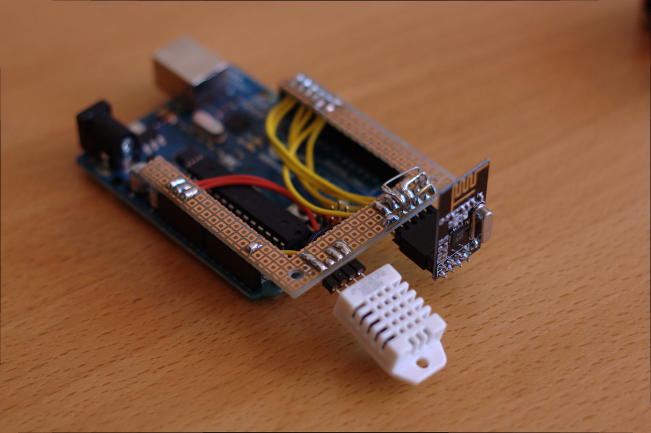
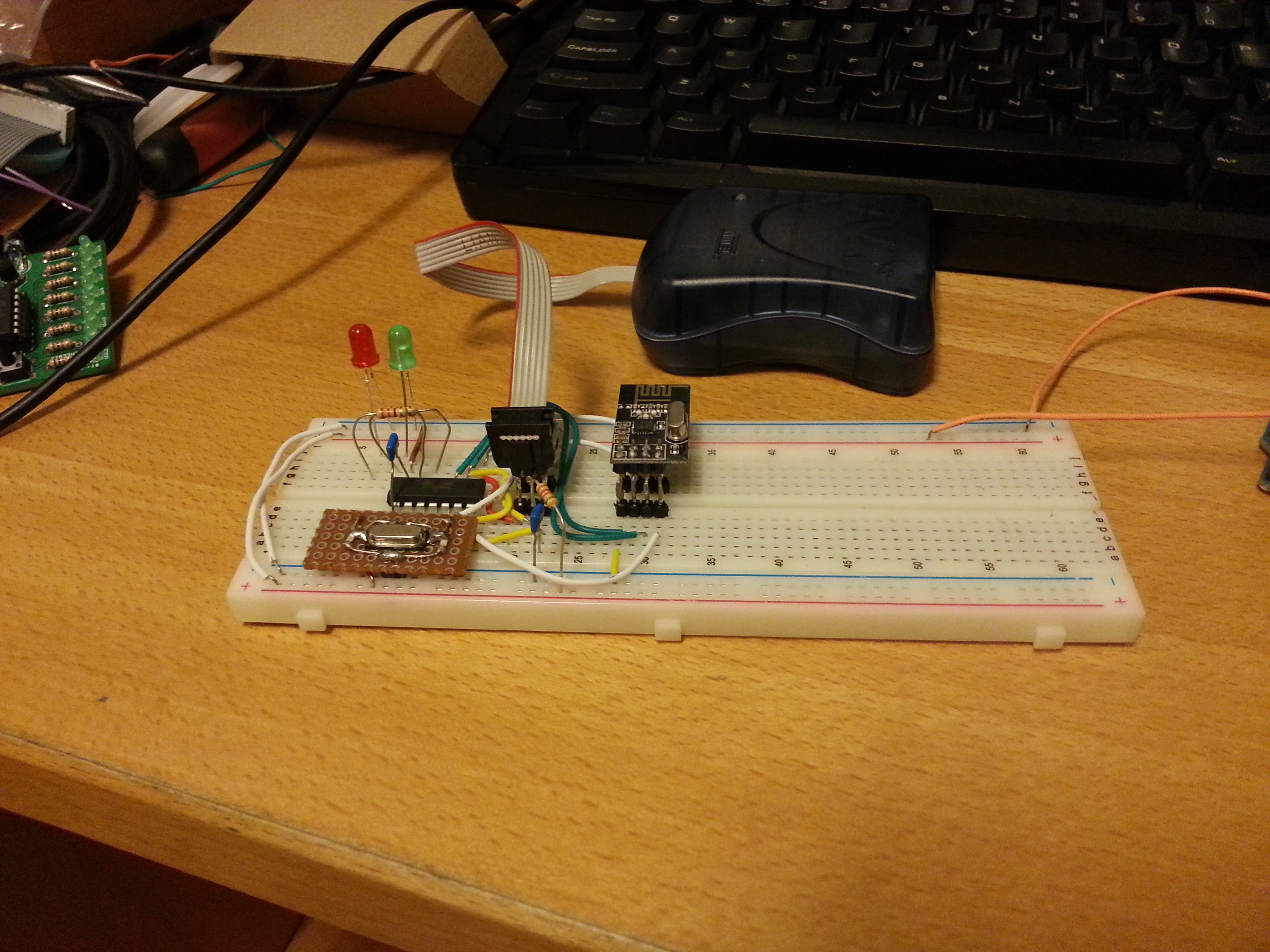
The rest of the prototype was an Arduino Uno, but any old Arduino will do.
The protocols
In parallel with my prototype Arduino setup, I also hooked up my logic analyzer (a cheap Cypress-based Saleae Logic clone) to eavesdrop on the serial data stream from the radio chip.
OBH
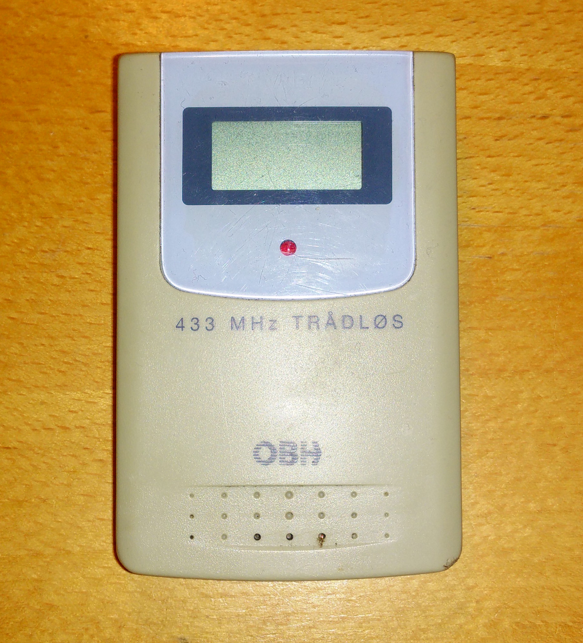
OBH unit
The protocol appears to be the one known as “Oregon Scientific V1”, which is a somewhat old protocol exclusively used for temperature-only sensors.
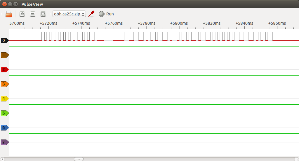
Signal sample
Europe Supplies Ltd. TX3
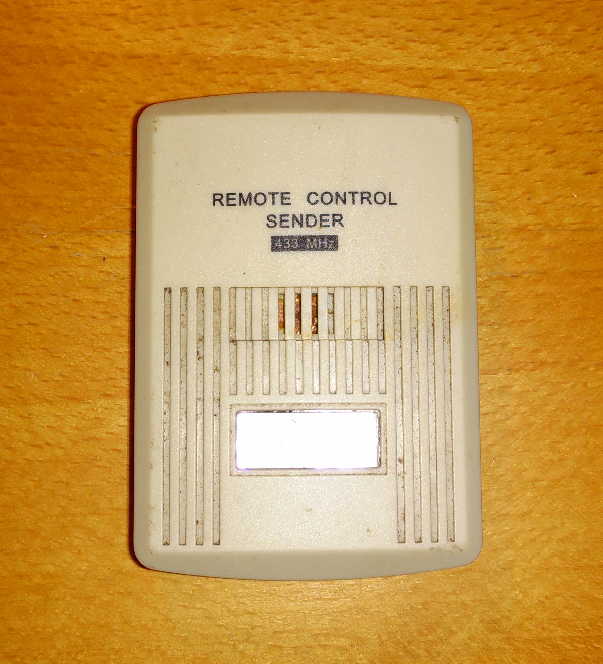
TX3 unit
Once you realize that this is identical to a LaCrosse TX3, you are done. This is a very popular sensor and its protocol is quite well known. It is unfortunately not the TX3-TH variety that also reports relative humidity, but at this price (free) I’ll take it.
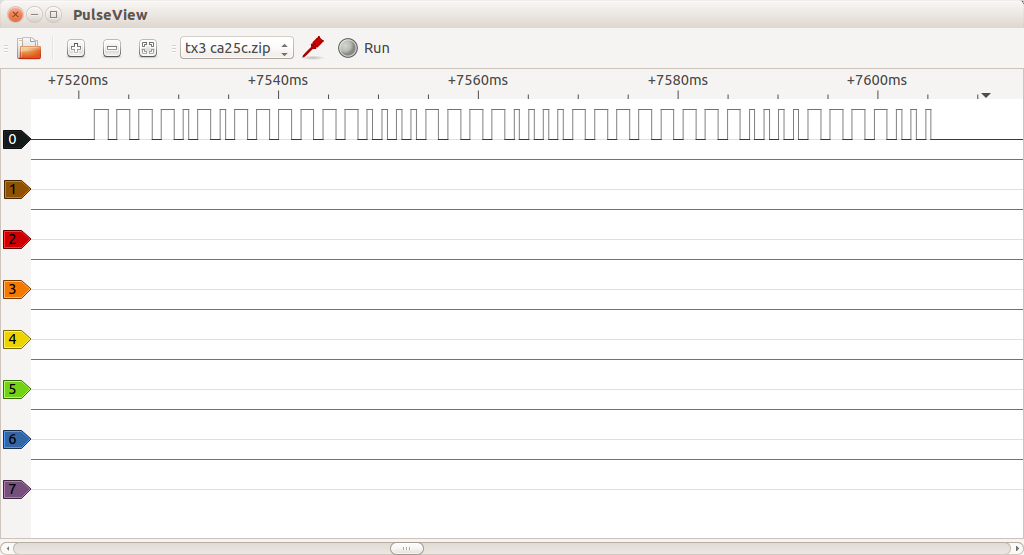
Signal Sample
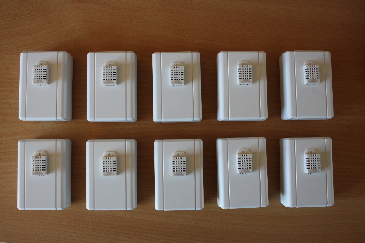
Unbranded unit

Unbranded unit
The protocol used by this unit is a bit different. At first glance it looks like identical short bursts until one looks at the intervals between the bursts. Short intervals mean 0 and long intervals mean 1. The unit sends 36 bits 7 times. My Google-fu didn’t find a lot of information about this one, but apparently the protocol seems to be very similar to the ones used by other unbranded china-devices. The so-called checksum used by this device is somewhere between useless and batshit insane.. Have a look in the code for the dirty details.
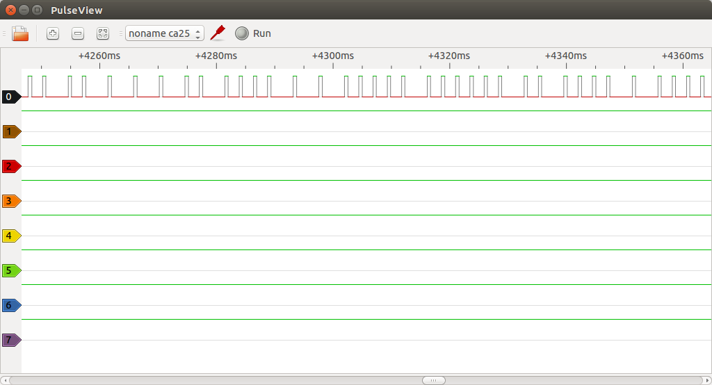
Signal sample
Bonus: Weber Style wireless BBQ thermometer (Model AW129)
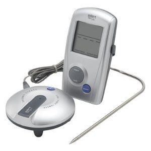
Weber AW129
Interestingly enough, this is just a rebranded Oregon Scientific unit that (unsurprisingly) uses the so-called “Oregon Scientific V2” protocol. To ensure data integrity, the signal is sent twice and each instance includes both a nibble checksum and a byte CRC8.
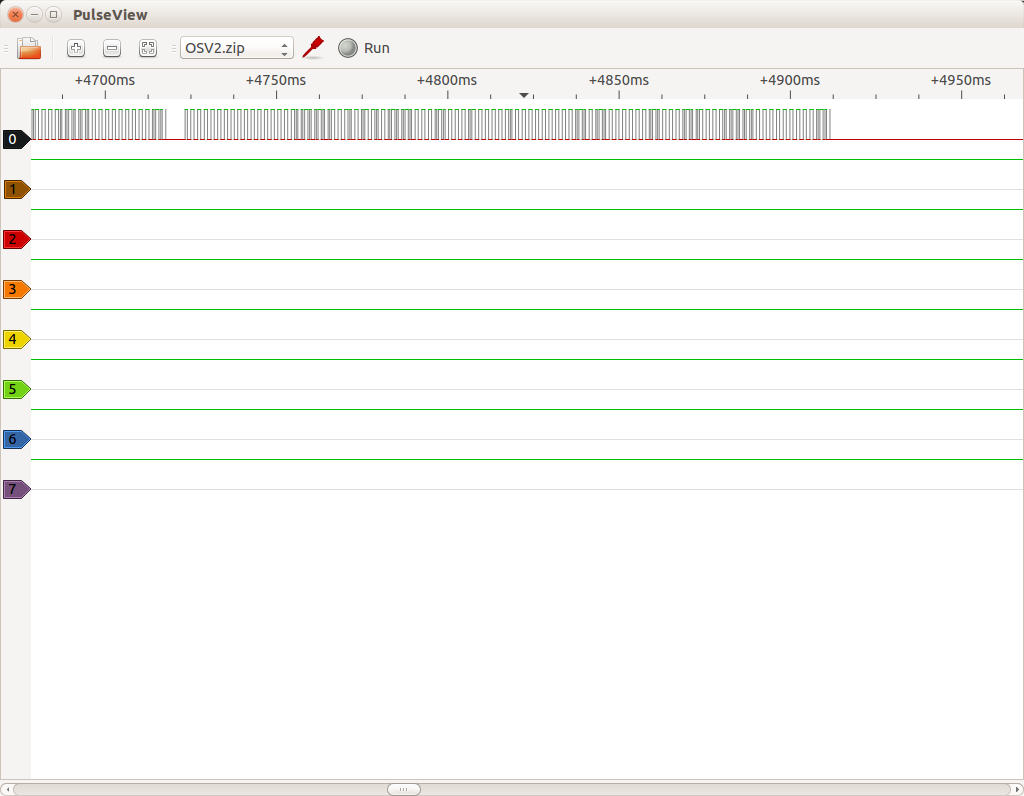
Signal sample
Having a wireless BBQ thermometer with data logging is actually very useful when doing slow-food like pulled pork where the smoker has to be monitored regularly over a period of several hours. It’s suddenly very easy to pick up on small changes in the rate of temperature increase inside the meat. This enables very fine-grained control of the air vents in the smoker as well as an indication if more coal or water is needed. Finally, it allows me to accurately predict several hours in advance when the meat will be done.

Pulled pork
I have no idea why a relatively nice wireless thermometer like this one is shipped with such a crappy receiver. Main problems include:
- There is no way of setting user-defined temperature alarms. The unit is shipped with a small number of factory presets depending on the type of meat and doneness, but the selection is extremely limited.
- The transmitter sends quite accurate readings with a resolution of 0.1 degrees Celcius, but the receiver unit just rounds this number to the nearest integer. This may be OK for most use-cases, but it’s very annoying for me when I want to keep a close watch on things.
- Sound alarms cannot be changed/muted.
But at least I’m happy that I can make my own receiver this way. 🙂
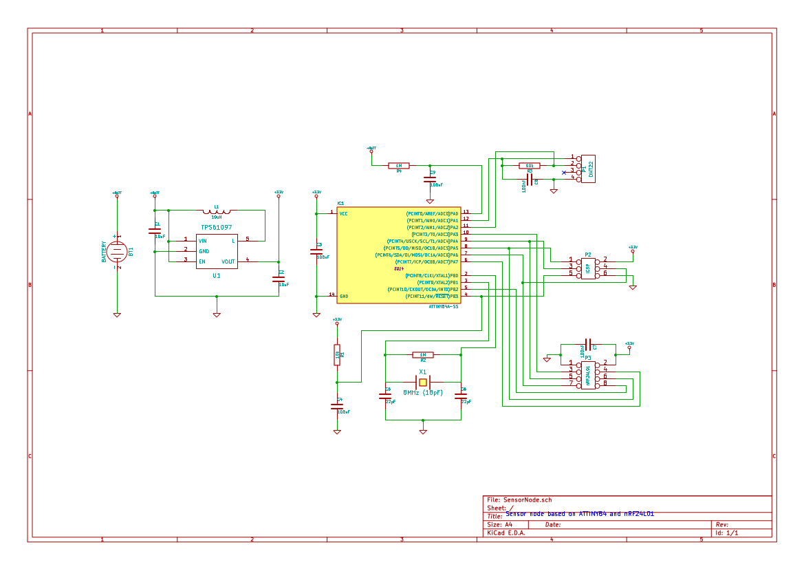
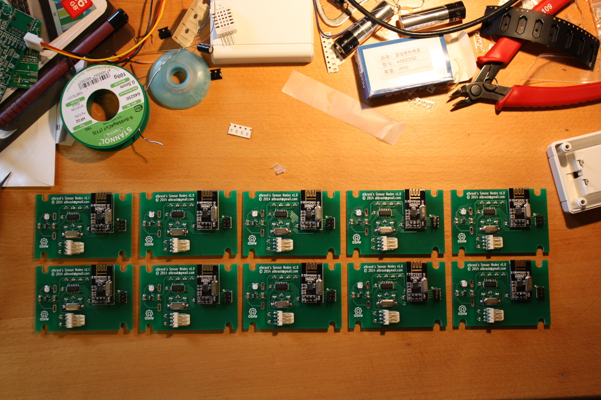
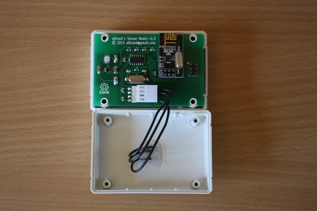
Porting to the ATtiny84 and adding 433MHz capability to RPIWeather
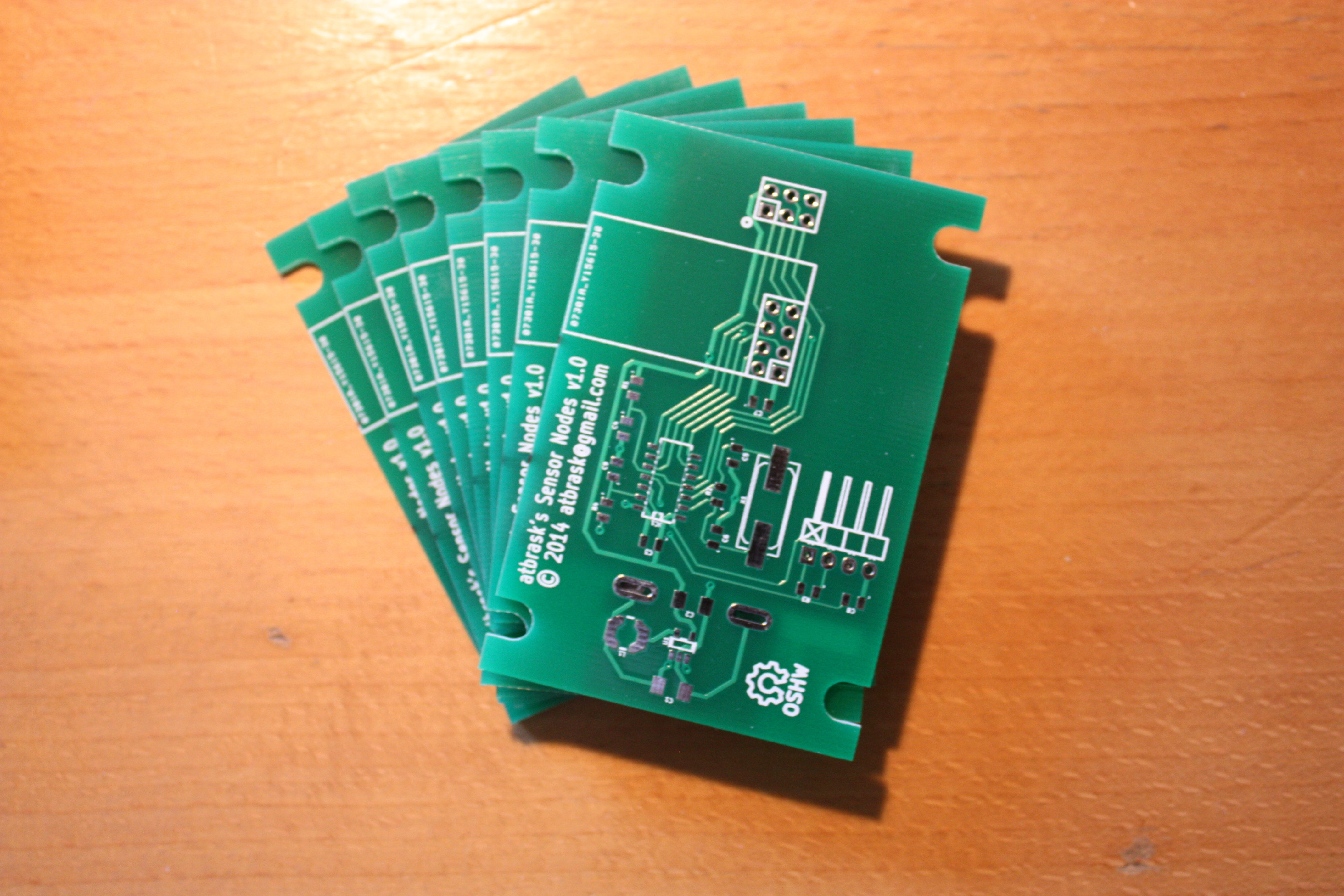
I had a few DIP ATtiny84s left over from the prototype phase of my own sensor nodes. Using one of these I was able to make a sufficiently compact module that listens for these known data packets on 433MHz and then forwards them to my Raspberry Pi using its internal UART RX pin. For this to work, I had to stop Linux from using the internal UART pins for a serial console interface. But it was a small price to pay, I think.
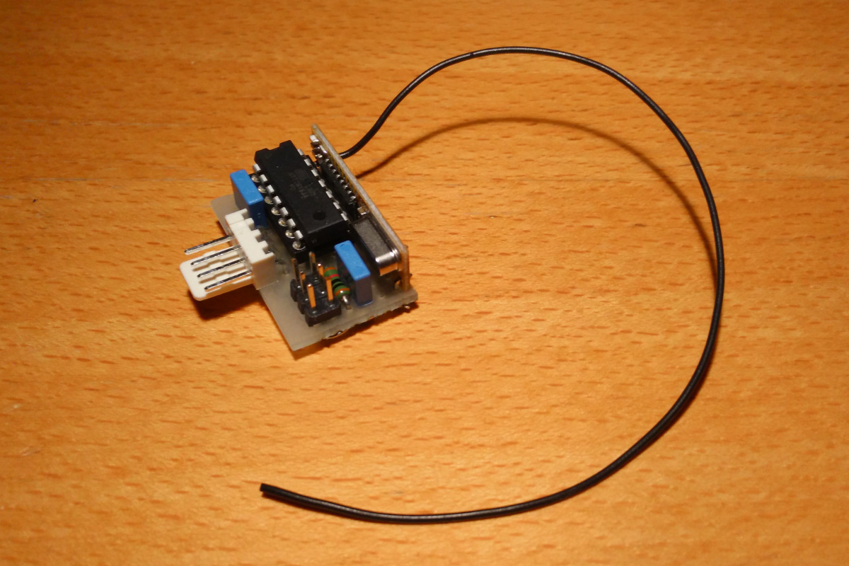
433MHz receiver
Originally, RPIWeather was designed exclusively with my own sensor nodes in mind. It actually triggered a bit of much needed refactoring to add this new capability to the code. Now the script starts a thread for the InfluxDB sender as well as a thread for each data source. These threads run totally independently and are only communicating through a concurrent queue object. At this point in time, RPIWeather supports three data sources which are connected to the Raspberry Pi in three different ways:
- My own 2.4GHz sensor nodes. The receiver is connected to the internal SPI pins.
- The above-mentioned 433MHz thermometer sensors. The receiver is connected to the internal UART RX pin.
- A Bosch BMP180 barometric sensor for measuring atmospheric pressure. It is connected to the internal I2C pins.
Show me the code!
All code and schematics can, as usual, be found on GitHub.
Happy Hacking! 🙂