In my last post, I described the various electronic components in my soon-to-be wireless thermo- and hygrometer. In this post, we’ll look at how to wire up some prototype perf boards.
Connecting an nRF24L01 module and a DHT22 sensor to an Arduino
An nRF24L01 radio module communicates with its host using SPI. Luckily for us, the Arduino (as well as most of the Atmel AVR chips in general) supports SPI directly in the hardware. The hardware SPI pins on the Arduino UNO are digital pins 11 (MOSI), 12 (MISO), and 13 (SCK). Furthermore, we need to wire up the radio module’s pins for CSN (Chip Select), CE (Chip Enable), VCC (3.3V), and GND. There’s also a pin called IRQ, but it seems to be used less commonly. All I/O pins are 5V tolerant, but VCC must not be above 3.6V according to the datasheet. This means that we don’t need to have a level-converter chip in order to use the radio module with an Arduino.
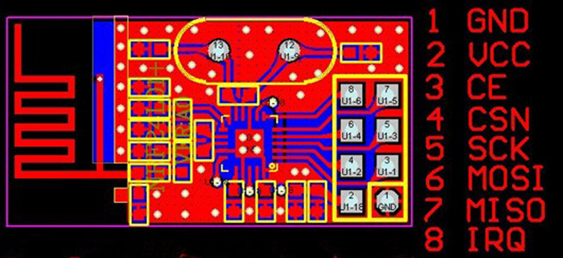
nRF24L01
I connected the module to my Arduino board like this:
| nRF24L01 pin: | Arduino pin: |
| 1 (GND) | GND |
| 2 (VCC) | 3.3V |
| 3 (CE) | Digital pin 9 |
| 4 (CSN) | Digital pin 10 |
| 5 (SCK) | Digital pin 13 |
| 6 (MOSI) | Digital pin 11 |
| 7 (MISO) | Digital pin 12 |
| 8 (IRQ) | Digital pin 8 |
Please note that the SPI pins are totally different on Arduino Leonardo boards, where they can only be accessed through the ICSP pin header. Backward compatibility FTW…
The DHT22 sensor is much simpler to hook up. It has four pins, but we only need three of them. I would have liked to use one of the remaining “traditional” digital pins on the Arduino, but due to the infamous pin header alignment bug, it’s much easier to reconfigure one of the analog input pins as a digital pin when using perf board. I have used pin A5, which is also known as digital pin 19.
| DHT22 pin: | Arduino pin: |
| 1 (VCC) | 5V (3.3V would probably also work) |
| 2 (DATA) | Digital pin 19 |
| 3 (N/C) | – |
| 4 (GND) | GND |
According to the datasheet, there’s supposed to be a pull-up resistor from the data pin to VCC. In practice it seems that the weak internal pull-up in the ATMEGA chip is enough. The sensor uses a weird 1-wire protocol on the data-pin, but fortunately we have the library provided by Adafruit.
With this knowledge it is just a matter of finding a suitable piece of perf board and the various needed bits and pieces. I must say that I never thought I would find a purpose for this exact piece of scrap perf board, but in this case it’s perfect.
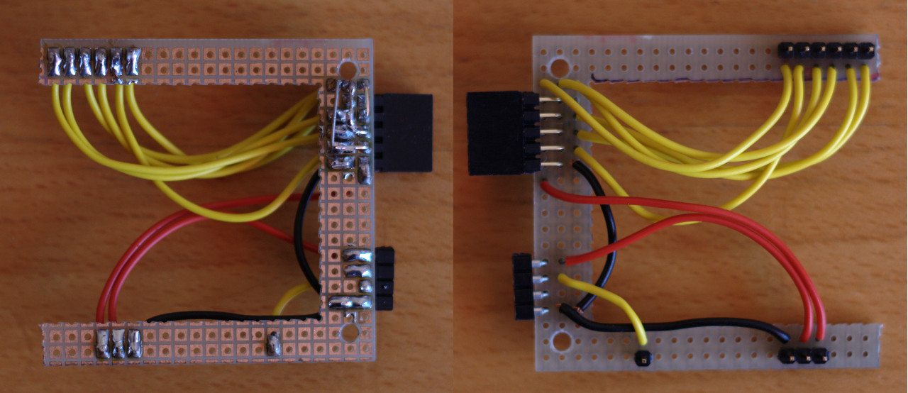
Arduino shield
When mounted it looks like this:
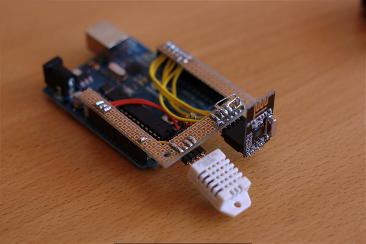
Arduino with nRF24L01 and DHT22
Connecting an nRF24L01 module to a Raspberry PI
Now we are ready for part two of this post. Again, we are going to use the hardware SPI port provided by the hardware. All the pins we need are located in the big 26-pin P1 header. There’s a nice write-up about P1 (and the other headers) on eLinux.org. I have connected the nRF24L01 module like this:
| nRF24L01 pin: | Raspberry PI pin (P1 header): |
| 1 (GND) | 20 (GND) |
| 2 (VCC) | 17 (3.3V) |
| 3 (CE) | 16 (GPIO 23) |
| 4 (CSN) | 18 (GPIO 24) |
| 5 (SCK) | 23 (SCLK / GPIO 11) |
| 6 (MOSI) | 19 (MOSI / GPIO 10) |
| 7 (MISO) | 21 (MISO / GPIO 9) |
| 8 (IRQ) | – |
This is mostly based on the documentation for this code I found while researching how to connect the parts. It is a Raspberry Pi port of a Beagleboard port of Maniacbug’s nice RF24 library for Arduino. The author writes that he doesn’t know if it works or not. Well it doesn’t. Not right away at least. It took some work to get running, but I’ll get back to that in the next post.
My adaptor board:
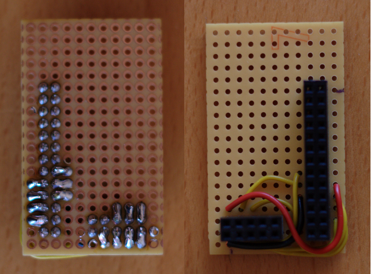
nRF24L01 adaptor board for Raspberry Pi
And mounted on the Pi with a radio module:
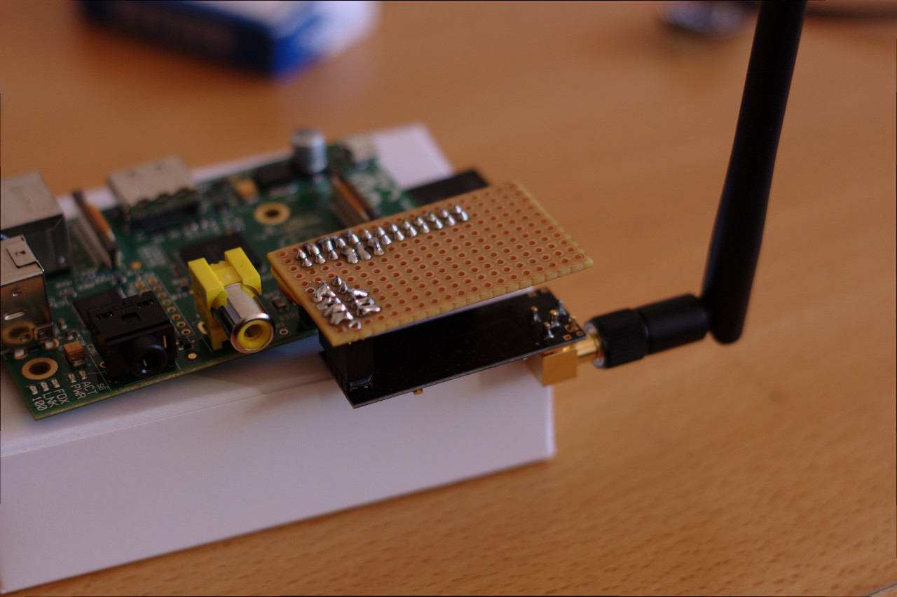
Mounted nRF24L01 adaptor board on Raspberry Pi
That’s it! Our prototype hardware is finished. In the next post I’ll explain how to get a simple ping/pong test working.
0 Comments