Using the hardware on an Arduino UNO

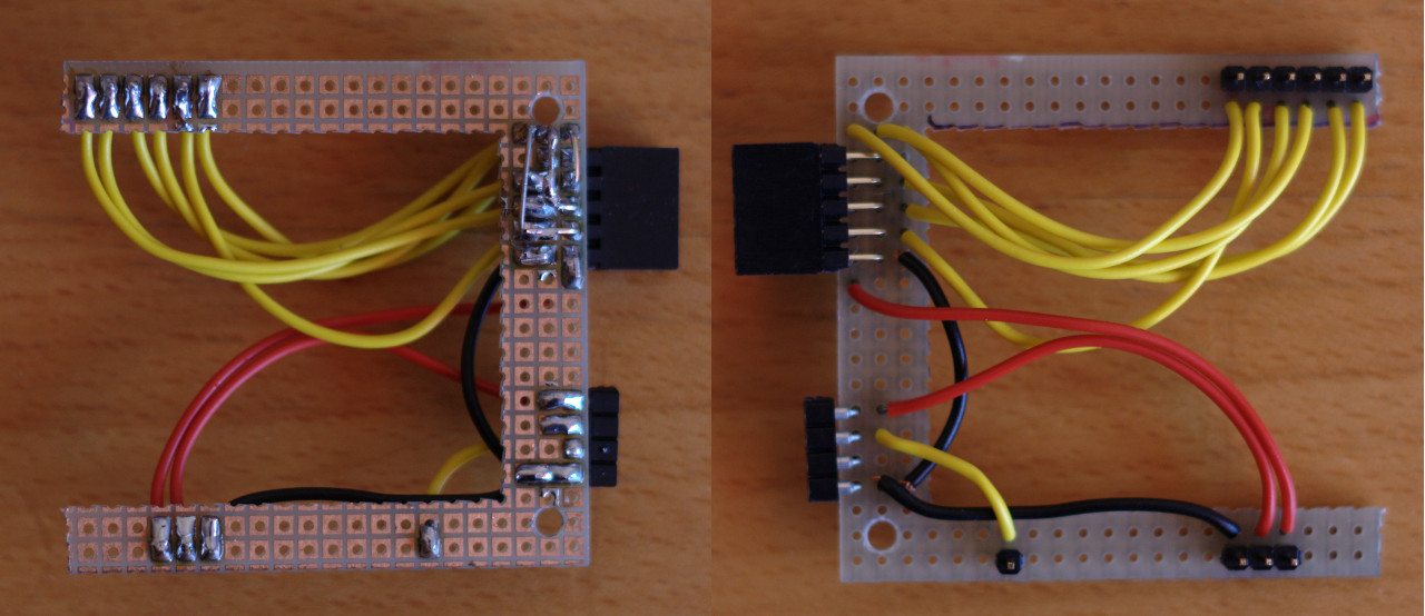
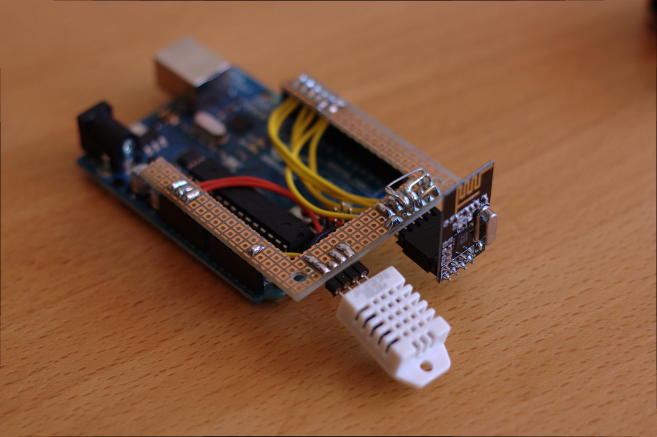
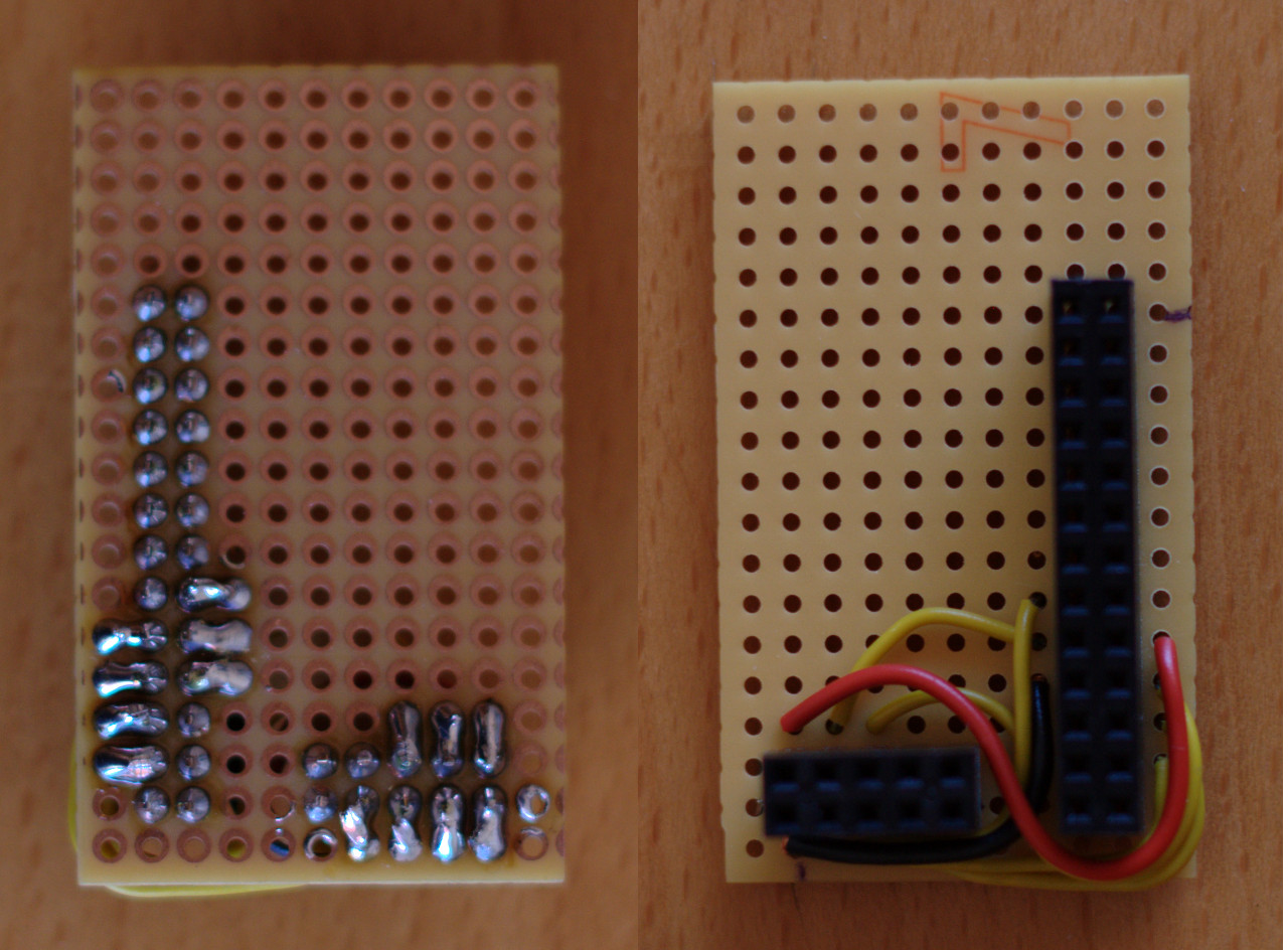
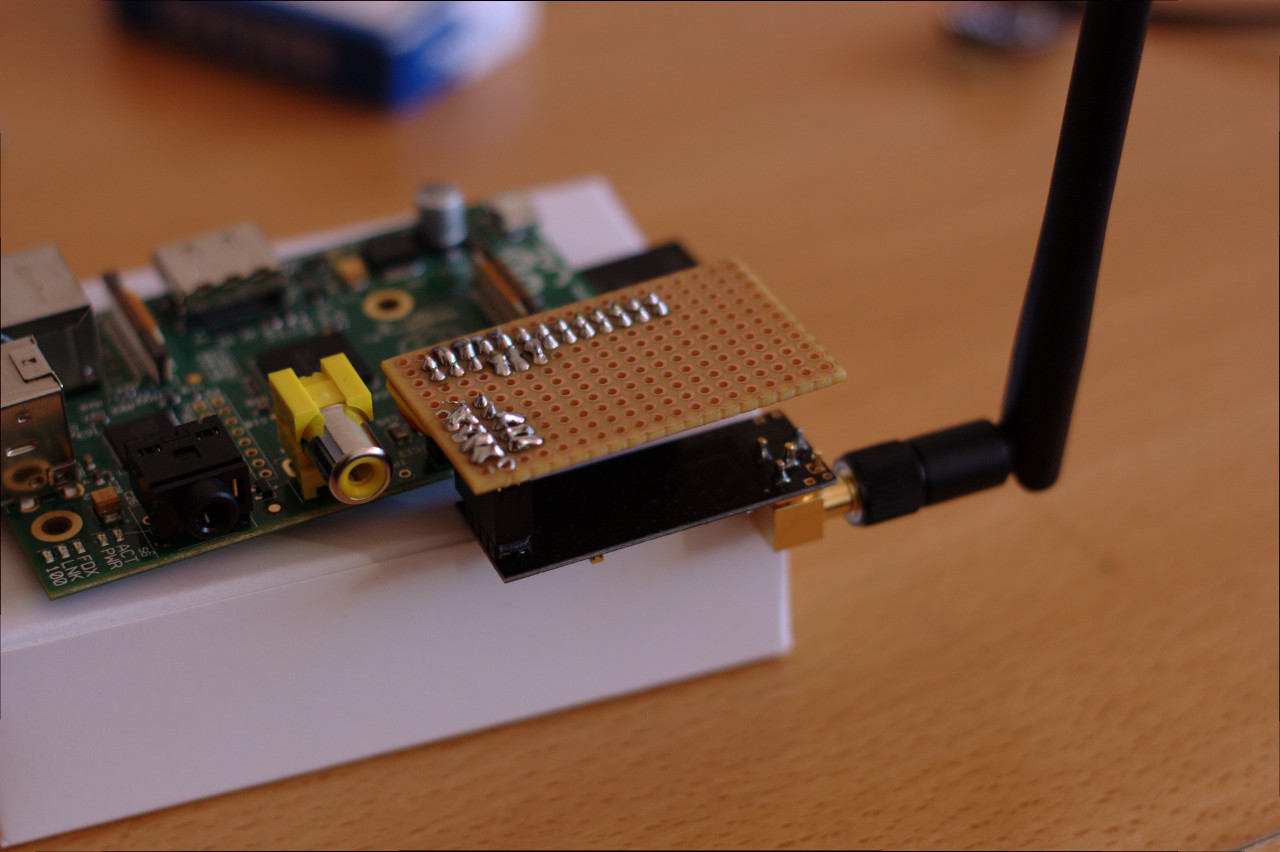
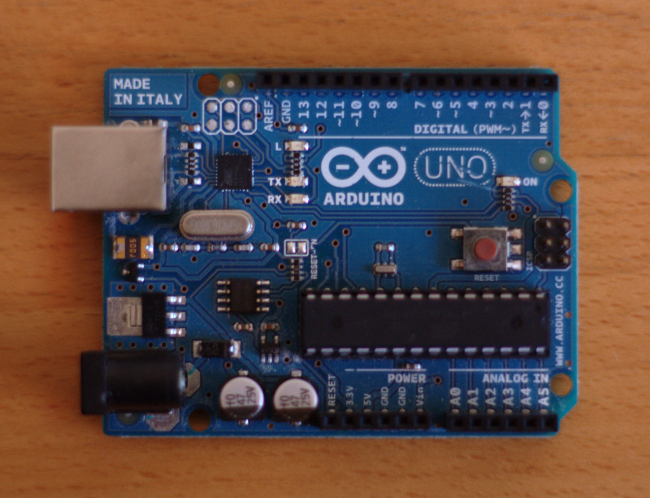
In this post we’ll go though what it takes to configure some Arduino libraries for the nRF24L01 modules and the DHT22 sensors. The hardware will in both cases be an Arduino UNO with the perf board shield described in my last post.

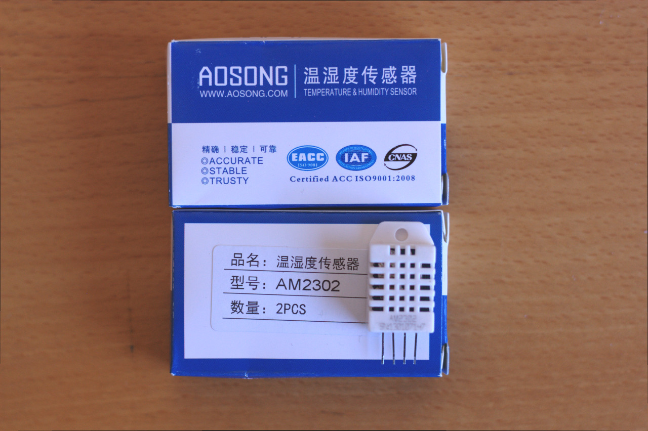
How to probe a DHT22 sensor from an Arduino

Let’s start by looking at how to talk to a DHT22. The DHT22 sensor uses a homemade 1-wire protocol for communicating with its host. The data transmission is initiated by the host by pulling the data pin low for 20 ms. Then the host pulls the data pin high for 40 ms. Finally, the sensor will transmit 40 bits by pulsing the data pin. Short pulses (26-28 microseconds) mean 0 and long pulses (70 microseconds) mean 1. Bytes 0 and 1 are the relative humidity and bytes 2 and 3 are the temperature. In both cases the first byte is the integral part while the second byte is the decimal part. The final byte is a checksum, which is simple the least significant byte of the sum of the previous 4 bytes. See the data sheet for more details on this.

DHT22 protocol

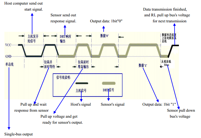
DHT22 handshake (as shown in the data sheet)

Luckily, all the hard work has been taken care of. To get started, grab a copy of Adafruit’s DHT22 library and unpack it to your Arduino library folder. Then open the Arduino IDE and open the DHT/DHTtester example. The only piece of configuration needed is which pin the sensor’s data pin is connected to. In my case it is analog input pin A5, which can also be used as digital pin 19. I simply changed #define DHTPIN 2 to #define DHTPIN 19. Upload the compiled code and open the serial monitor. Remember to set the baud rate to 9600. If all went well, you should be greeted with something like this:

DHTxx test!
Humidity: 23.90 % Temperature: 26.20 *C
Humidity: 23.80 % Temperature: 26.20 *C

The library code looks simple enough to optimize for size. We don’t need all the bells and whistles for our sensor nodes.

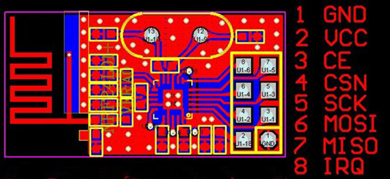
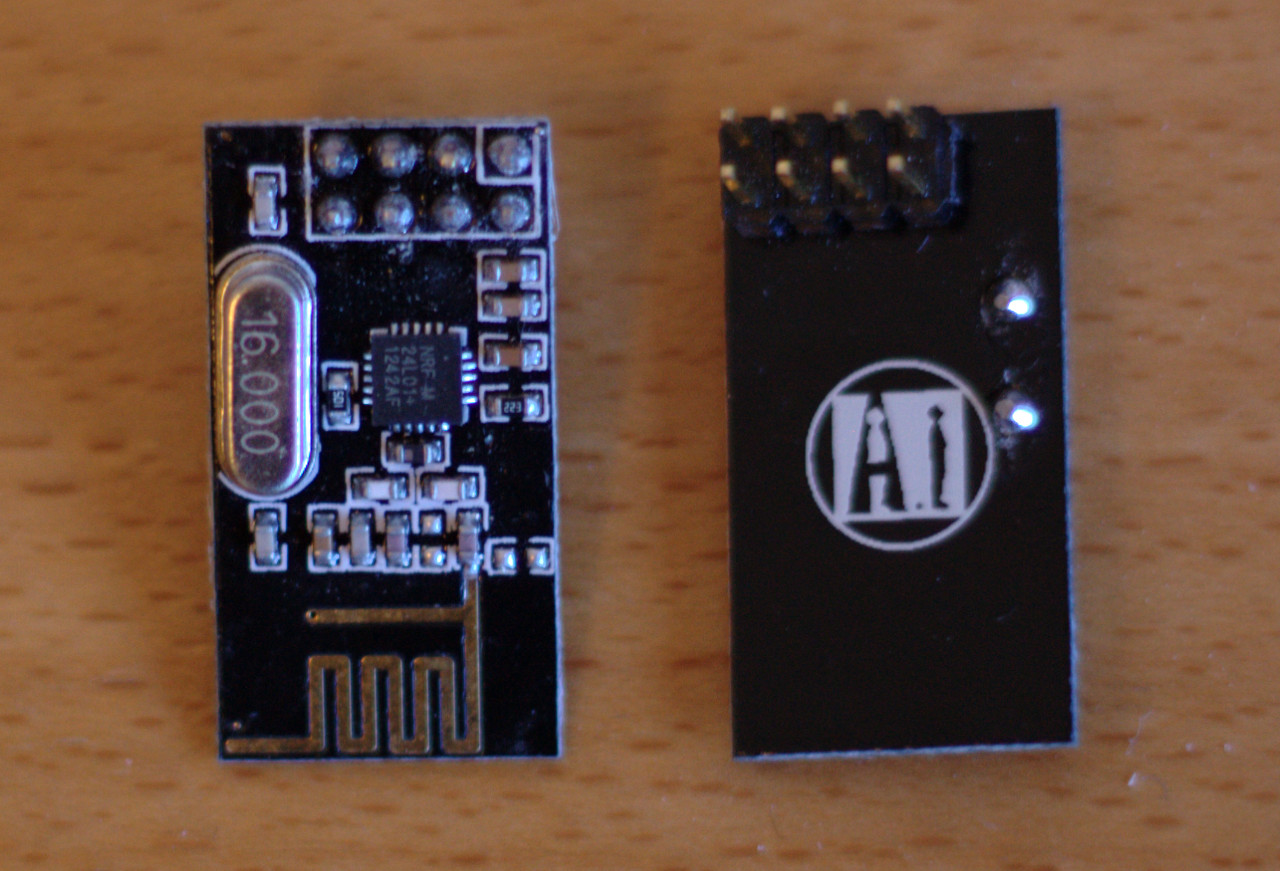
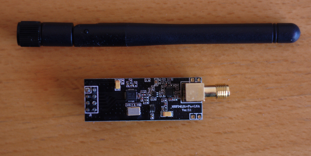
How to make a configure and use an nRF24L01 radio module from an Arduino

There is a great data sheet for the chip at Nordic Semiconductor’s website. From this data sheet it’s entirely possible to write a library from scratch. But for prototyping it’s better to stand on the shoulders of giants instead of re-inventing the wheel. Let’s use an existing library.

As I’ve mentioned earlier, there are already great libraries for this online. Basically, there are two worth mentioning: Maniacbug’s RF24 library and the smaller Mirf library. We will be using the former as it’s the most complete of the two. I have noticed that there are several forks of this library on GitHub, so it may be best to shop around a bit to find the best match for our purposes. Download a zip and expand the contents to your Arduino libraries folder.

We are going to test radio connectivity using the RF24/pingpair_dyn example. There are lots of settings to configure, but as a bare minimum we need to configure which pin is CE, which pin is CSN, and the role of the node (i.e. if we are the pinging part or the ponging part of the pair). Conveniently, the defaults for CE and CSN are the ones I’m using (i.e. digital pins 9 and 10). This can be changed in line 26 where it says RF24 radio(9,10);. Remember that no matter which pins you use, you must have pin 10 configured as an output for the SPI hardware to work in master mode. Else, it will run in slave mode and the code won’t work.

The default behavior for the RF24/pingpair_dyn example is to be the pinging part. Let’s just keep it that way and configure the Raspberry Pi to be the ponging part. Now try to compile and upload the code. Without a pong-partner, the pings will just time out, but at least we know something is working. Remember that this test uses 57600 baud per default when using the serial monitor. The output should look something like this:

RF24/examples/pingpair_dyn/
ROLE: Ping out
STATUS = 0x0e RX_DR=0 TX_DS=0 MAX_RT=0 RX_P_NO=7 TX_FULL=0
RX_ADDR_P0-1 = 0xf0f0f0f0e1 0xf0f0f0f0d2
RX_ADDR_P2-5 = 0xc3 0xc4 0xc5 0xc6
TX_ADDR = 0xf0f0f0f0e1
RX_PW_P0-6 = 0x20 0x20 0x00 0x00 0x00 0x00
EN_AA = 0x3f
EN_RXADDR = 0x03
RF_CH = 0x4c
RF_SETUP = 0x07
CONFIG = 0x0f
DYNPD/FEATURE = 0x3f 0x04
Data Rate = 1MBPS
Model = nRF24L01+
CRC Length = 16 bits
PA Power = PA_HIGH
Now sending length 4...Failed, response timed out.
Now sending length 6...Failed, response timed out.
Now sending length 8...Failed, response timed out.
Now sending length 10...Failed, response timed out.

If something is wrong (e.g. if the SPI interface has been configured incorrectly), the code will fail to recognize the radio. Then the output in the serial monitor will look like this:

RF24/examples/pingpair_dyn/
ROLE: Ping out
STATUS = 0xff RX_DR=1 TX_DS=1 MAX_RT=1 RX_P_NO=7 TX_FULL=1
RX_ADDR_P0-1 = 0x0000000000 0x0000000000
RX_ADDR_P2-5 = 0xff 0xff 0xff 0xff
TX_ADDR = 0xffffffffff
RX_PW_P0-6 = 0x00 0x00 0x00 0x00 0x00 0x00
EN_AA = 0xff
EN_RXADDR = 0xff
RF_CH = 0xff
RF_SETUP = 0xff
CONFIG = 0xff
DYNPD/FEATURE = 0x00 0x00
Data Rate = 1MBPS
Model = nRF24L01
CRC Length = 16 bits
PA Power = PA_HIGH
Now sending length 4...Got response size=255 value=ÿÿÿÿÿÿÿÿÿÿÿÿÿÿÿÿÿÿÿÿÿÿÿÿÿÿÿÿÿÿÿ
Now sending length 6...Got response size=255 value=ÿÿÿÿÿÿÿÿÿÿÿÿÿÿÿÿÿÿÿÿÿÿÿÿÿÿÿÿÿÿÿ
Now sending length 8...Got response size=255 value=ÿÿÿÿÿÿÿÿÿÿÿÿÿÿÿÿÿÿÿÿÿÿÿÿÿÿÿÿÿÿÿ
Now sending length 10...Got response size=255 value=ÿÿÿÿÿÿÿÿÿÿÿÿÿÿÿÿÿÿÿÿÿÿÿÿÿÿÿÿÿÿ

Assuming all went well, we are now done testing the Arduino libraries. Ultimately, they will be used as inspiration for the sensor node firmware. My next post will be about getting the Raspberry Pi to talk to the radio modules. In the end we should have a working ping/pong test running.

Making prototype perf board hardware

In my last post, I described the various electronic components in my soon-to-be wireless thermo- and hygrometer. In this post, we’ll look at how to wire up some prototype perf boards.

Connecting an nRF24L01 module and a DHT22 sensor to an Arduino

An nRF24L01 radio module communicates with its host using SPI. Luckily for us, the Arduino (as well as most of the Atmel AVR chips in general) supports SPI directly in the hardware. The hardware SPI pins on the Arduino UNO are digital pins 11 (MOSI), 12 (MISO), and 13 (SCK). Furthermore, we need to wire up the radio module’s pins for CSN (Chip Select), CE (Chip Enable), VCC (3.3V), and GND. There’s also a pin called IRQ, but it seems to be used less commonly. All I/O pins are 5V tolerant, but VCC must not be above 3.6V according to the datasheet. This means that we don’t need to have a level-converter chip in order to use the radio module with an Arduino.

nRF24L01

nRF24L01

I connected the module to my Arduino board like this:

nRF24L01 pin: Arduino pin:
1 (GND) GND
2 (VCC) 3.3V
3 (CE) Digital pin 9
4 (CSN) Digital pin 10
5 (SCK) Digital pin 13
6 (MOSI) Digital pin 11
7 (MISO) Digital pin 12
8 (IRQ) Digital pin 8

Please note that the SPI pins are totally different on Arduino Leonardo boards, where they can only be accessed through the ICSP pin header. Backward compatibility FTW…

The DHT22 sensor is much simpler to hook up. It has four pins, but we only need three of them. I would have liked to use one of the remaining “traditional” digital pins on the Arduino, but due to the infamous pin header alignment bug, it’s much easier to reconfigure one of the analog input pins as a digital pin when using perf board. I have used pin A5, which is also known as digital pin 19.

DHT22 pin: Arduino pin:
1 (VCC) 5V (3.3V would probably also work)
2 (DATA) Digital pin 19
3 (N/C)
4 (GND) GND

According to the datasheet, there’s supposed to be a pull-up resistor from the data pin to VCC. In practice it seems that the weak internal pull-up in the ATMEGA chip is enough. The sensor uses a weird 1-wire protocol on the data-pin, but fortunately we have the library provided by Adafruit.

With this knowledge it is just a matter of finding a suitable piece of perf board and the various needed bits and pieces. I must say that I never thought I would find a purpose for this exact piece of scrap perf board, but in this case it’s perfect.

Arduino shield

Arduino shield

When mounted it looks like this:

Arduino with nRF24L01 and DHT22

Arduino with nRF24L01 and DHT22

Connecting an nRF24L01 module to a Raspberry PI

Now we are ready for part two of this post. Again, we are going to use the hardware SPI port provided by the hardware. All the pins we need are located in the big 26-pin P1 header. There’s a nice write-up about P1 (and the other headers) on eLinux.org. I have connected the nRF24L01 module like this:

nRF24L01 pin: Raspberry PI pin (P1 header):
1 (GND) 20 (GND)
2 (VCC) 17 (3.3V)
3 (CE) 16 (GPIO 23)
4 (CSN) 18 (GPIO 24)
5 (SCK) 23 (SCLK / GPIO 11)
6 (MOSI) 19 (MOSI / GPIO 10)
7 (MISO) 21 (MISO / GPIO 9)
8 (IRQ)

This is mostly based on the documentation for this code I found while researching how to connect the parts. It is a Raspberry Pi port of a Beagleboard port of Maniacbug’s nice RF24 library for Arduino. The author writes that he doesn’t know if it works or not. Well it doesn’t. Not right away at least. It took some work to get running, but I’ll get back to that in the next post.

My adaptor board:

nRF24L01 adaptor board for Raspberry Pi

nRF24L01 adaptor board for Raspberry Pi

And mounted on the Pi with a radio module:

Mounted adaptor board

Mounted nRF24L01 adaptor board on Raspberry Pi

That’s it! Our prototype hardware is finished. In the next post I’ll explain how to get a simple ping/pong test working.

New Project: Wirelesss thermo- and hygrometer

Let’s start this blog out by looking at a project..

So, wouldn’t it be cool to have the ultimate open source (well, mostly) indoor/outdoor thermo- and hygrometer with multiple wireless sensors and a sleek HTML5 based interface? Of course it would! I’m not the first one to make one of these. In fact, the guy who made the Arduino library for the radio modules I’m going to use has made something very similar: Low-Power Wireless Sensor Node

I often pick my projects in order to learn some new skill or technology. But in this case there’s also a potentially useful gadget in the end. The new technologies for me this time will be energy-efficient embedded design, wireless communications, backend design (perhaps even some NoSQL), and a dynamically updated HTML5 frontend. Oh, and responsive design. It must look nice on both “real” computers and tablets/phones.

Some preliminary features and specifications:

  • Raspberry PI as base station
  • nRF24L01+ based radio modules
  • DHT22 temperature & humidity sensors
  • Battery-powered Atmel ATTiny based sensor boards
  • Arduino Uno as prototype platform for the sensor boards
  • HTML5 based frontend (WebSockets, SVG graphics, …)
  • Database backend that stores all measurements (perhaps MongoDB)

Let’s look over these features one by one.

Raspberry PI as base station

RPI

Raspberry PI – Model B

Every hobby project needs either a Raspberry PI or an Arduino to score blogosphere points, amirite? Besides, it’s also offers good value for money. At Open Space Aarhus, my friendly local hackerspace, we recently did a group-buy of these. We ended up paying 275 DKK (approx. $47) including taxes and shipping for a B-model. That’s not too bad considering the Danish 25% VAT..

But why a Raspberry Pi, you might ask. Well, besides its relatively powerful CPU, good Linux support, and built-in LAN interface, it also provides hardware SPI pins in its GPIO header. This is very useful for communicating with the radio modules described below.

nRF24L01+ based radio modules

nRF24L01+ module

nRF24L01+ module

I used to think that 2.4GHz wireless modules were too expensive for a project like this. Not anymore! These bad boys cost me $1.20 apiece on Ebay. I got 10 of them, so if I don’t break any I’ll end out with 10 wireless sensor modules. The nRF24L01 chip (and cheap modules) has become quite popular among hobbyists it seems. Well, count me in. So instead of messing around with RF design and other low-level radio stuff, I can concentrate on a nice and tidy SPI based interface where all the gritty details have been taken care of. It’s even battery-friendly due to its multiple sleep modes. More on this later…

nRF24L01+ module with PA and LNA

nRF24L01+ module with PA and LNA

For the base station I’ve chosen a much more potent radio module. It uses the same chip, but with additional amplifiers and a proper antenna. It cost me more than all the other radio modules combined, but it’s an attempt at extending the range of the system. Besides the amplifiers, the board is more or less identical to the others. The pin header is exactly the same.

Of course, someone already implemented an Arduino library for these modules: Getting Started with nRF24L01+ on Arduino

It has even been ported to work with the SPI hardware on the Raspberry PI: RF24RP

It took me a bit of debugging to get the example code running on the Pi. I’ll get back to that in a later post.

DHT22 temperature & humidity sensors

AM2302

AM2302

There’s not much sense in making sensor nodes without sensors. I considered several alternatives until I noticed the DHT22 sensor type. It’s a combined temperature and humidity sensor with a very good range (0…100% RH and -40…125 degrees Celsius) and adequate precision for this purpose (+/- 2-5% RH and +/- 0.5 degrees Celcius).

I found a great deal on AM2302 sensors on Ebay. They are basically the same as DHT22. My preliminary tests indicate that they are sufficiently accurate.

Adafruit has made an Arduino library for it: DHT-sensor-library

Battery-powered Atmel ATTiny based sensor boards

In order for this project to be a success, the sensor nodes must be able to run for several months between battey changes. It might be better to pursue other architectures than Atmel AVR (e.g. the very power efficient TI MSP430 series), but the Atmel MCUs are familiar to me.

At some point I will draw up some PCBs for this. Stay tuned…

Arduino Uno as prototype platform for the sensor boards

Arduino Uno

Arduino Uno

At the early stages of the project, it’s nice to have a simple prototype platform. I’m using an Arduino for this. When the code starts to mature, I’ll switch to a custom prototype board based on an ATTiny chip.

HTML5 based frontend (WebSockets, SVG graphics, …)

Continuously updating sensor measurements provide a nice real-life data source for a dynamic HTML5 website. More on this later… 

Database backend that stores all measurements (perhaps MongoDB)

I want to store all measurements in order to make various statistics. Both simple stuff like the temperature development during the last 24 hours as well as more advanced calculations are interesting. More on this later…

Next stop: Make prototype perf board hardware