Some of the first posts on this blog were about how to interact with the famous nRF24L01 2.4GHz radio chipset from both an Arduino and a Raspberry Pi. Well.. Much have happened in the mean time, but at least I have managed to put together something using what I learned back then. I decided to make a wireless monitoring system for environmental data in and around our house with at least one sensor node in each room as well as a couple of sensors outside. It is called RPIWeather and you can get all the code and documentation by clicking the name. This post is just meant as a short summary.
RPIWeather consists of a bunch of wireless sensor nodes, a base station that collects the data packets, a database server, and one or more frontends. My goal has been to collect data at 5 minute intervals and keep it indefinitely for analysis, comparison, and visualization. This creates some demands for power efficiency and reliability, which I find interesting.
The sensor nodes
My first prototype was based around an Arduino and some proto-board and is described here, here, and here. It looked like this:
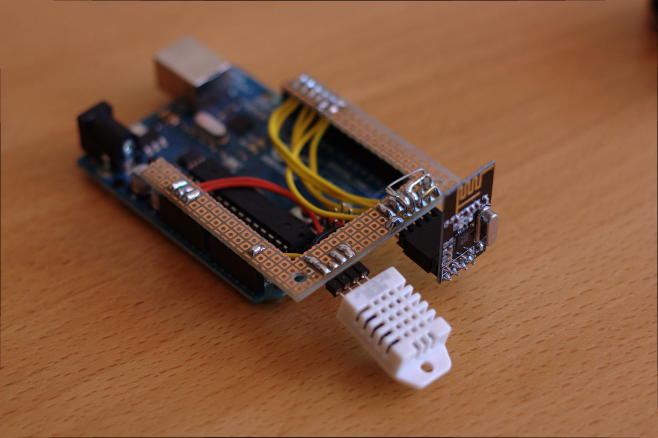
Arduino with nRF24L01 and DHT22
To keep things simple, clean, and small, I decided to ditch the Arduino platform and code in straight avr-libc for the ATtiny84 chip from Atmel. So I made another prototype, but this time with an ATtiny84 instead.
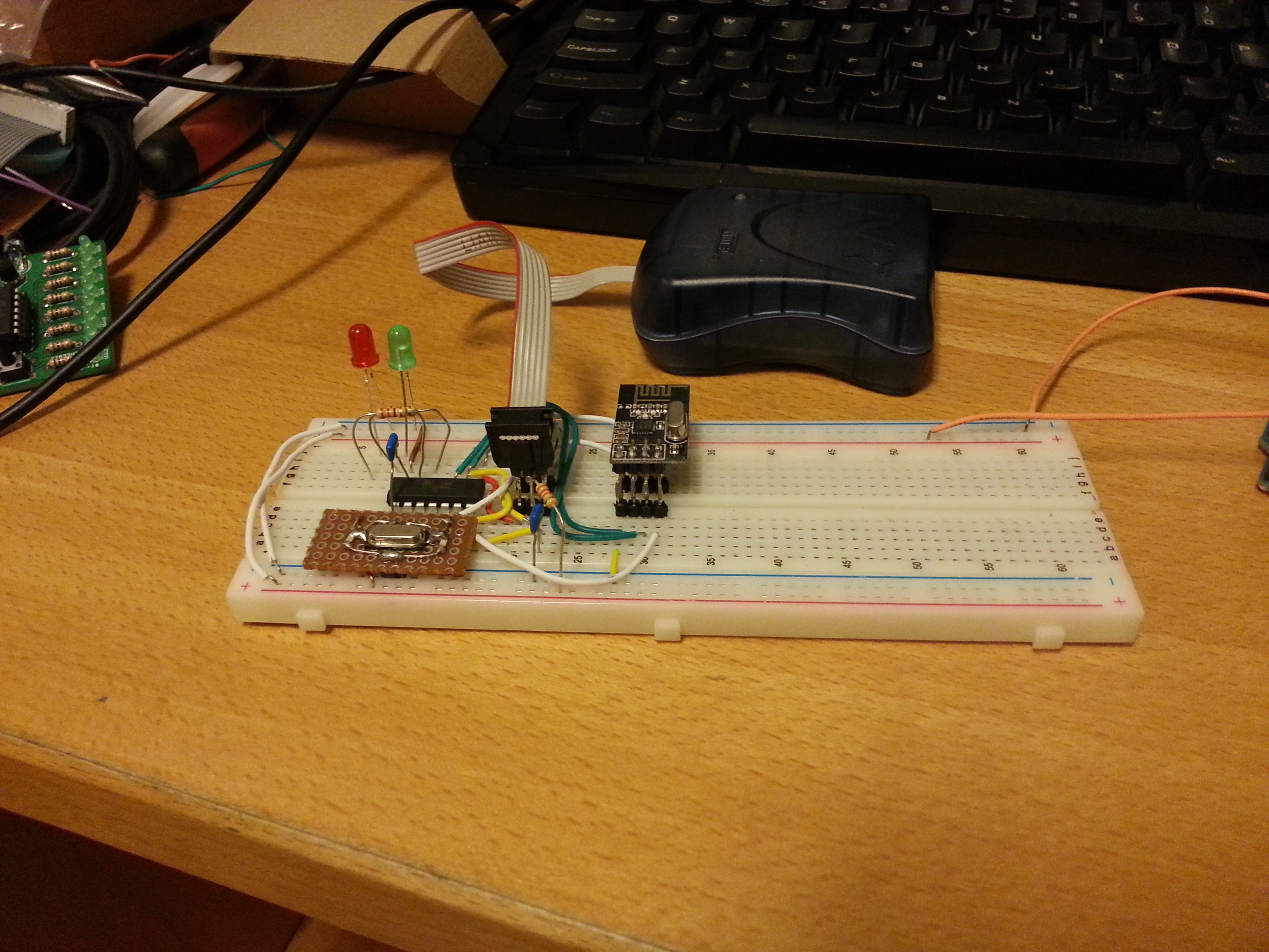
Partial prototype without the DHT22 sensor
Little by little a schematic emerged. Besides the radio, the sensor and the MCU, I also needed some sort of power supply. As the sensor nodes are to be distributed throughout the house, this implied battery power, but it couldn’t just be any old battery. The thing is that the radio chip can only tolerate up to 3.6v and the DHT22 sensor can only operate down to ~3v, which leaves a narrow band of usable voltages. A traditional voltage regulator would have burned though the batteries quite quickly, so I had to put in a switching boost converter. This way 2 AA NiMH batteries can deliver a reasonably stable 3.3v supply voltage for the circuit. Pro tip: when buying NiMH batteries, do yourself a favor and use the low self-discharge kind like Eneloop. In this use-case they will go for several months between charges.
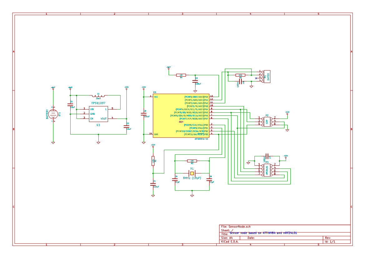
Schematic for the sensor nodes
With the schematic in place, I made a PCB layout and sent it to ITEAD for manufacturing. Here are a couple of pictures showing various stages of assembly. The funny shape of the boards was needed to make them fit snugly into some cool boxes from New Age Enclosures.
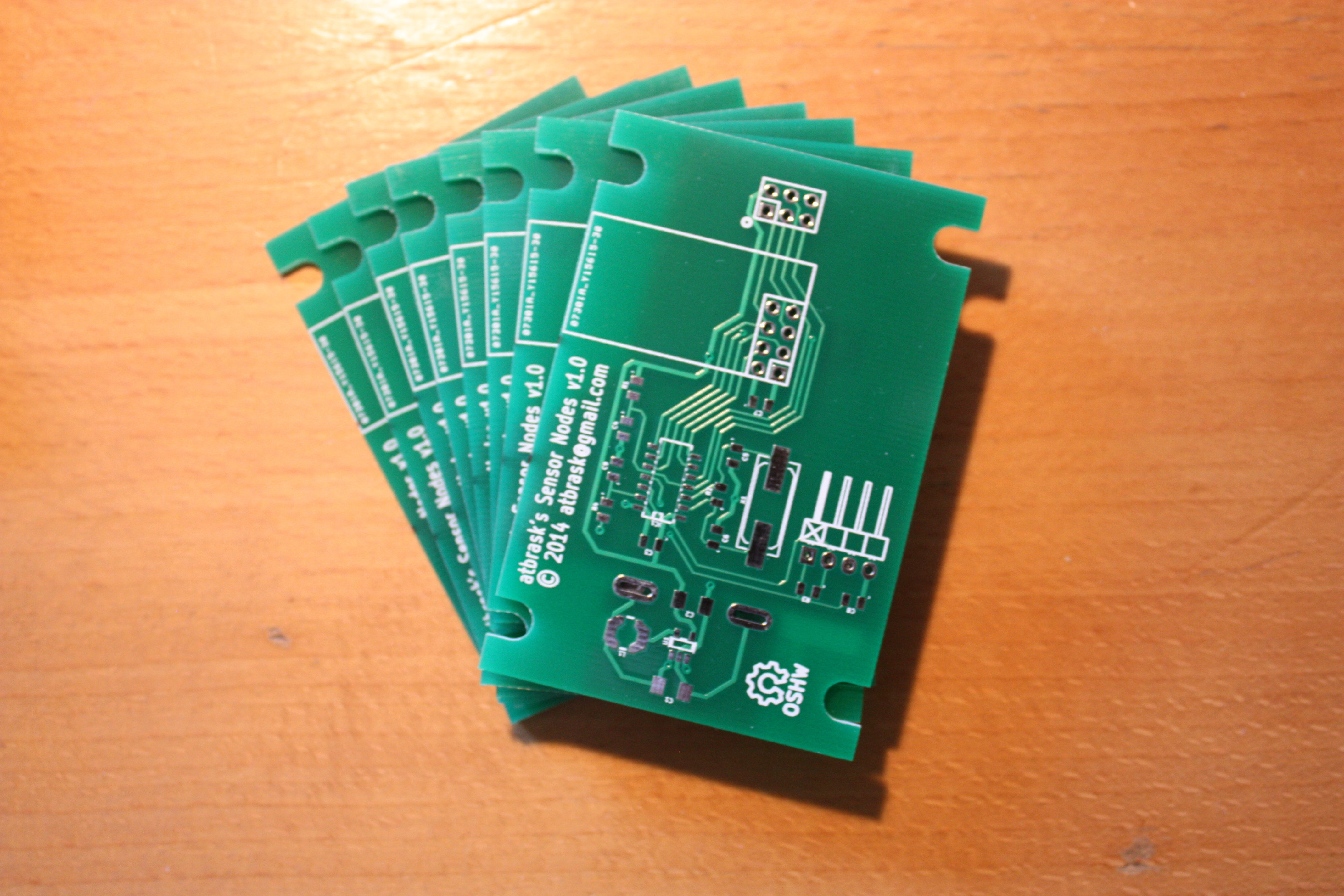
Sensor node PCBs
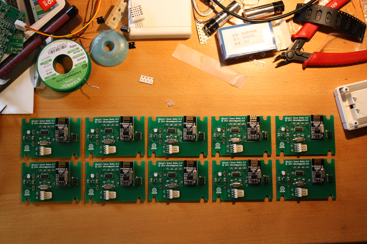
The first 10 finished boards
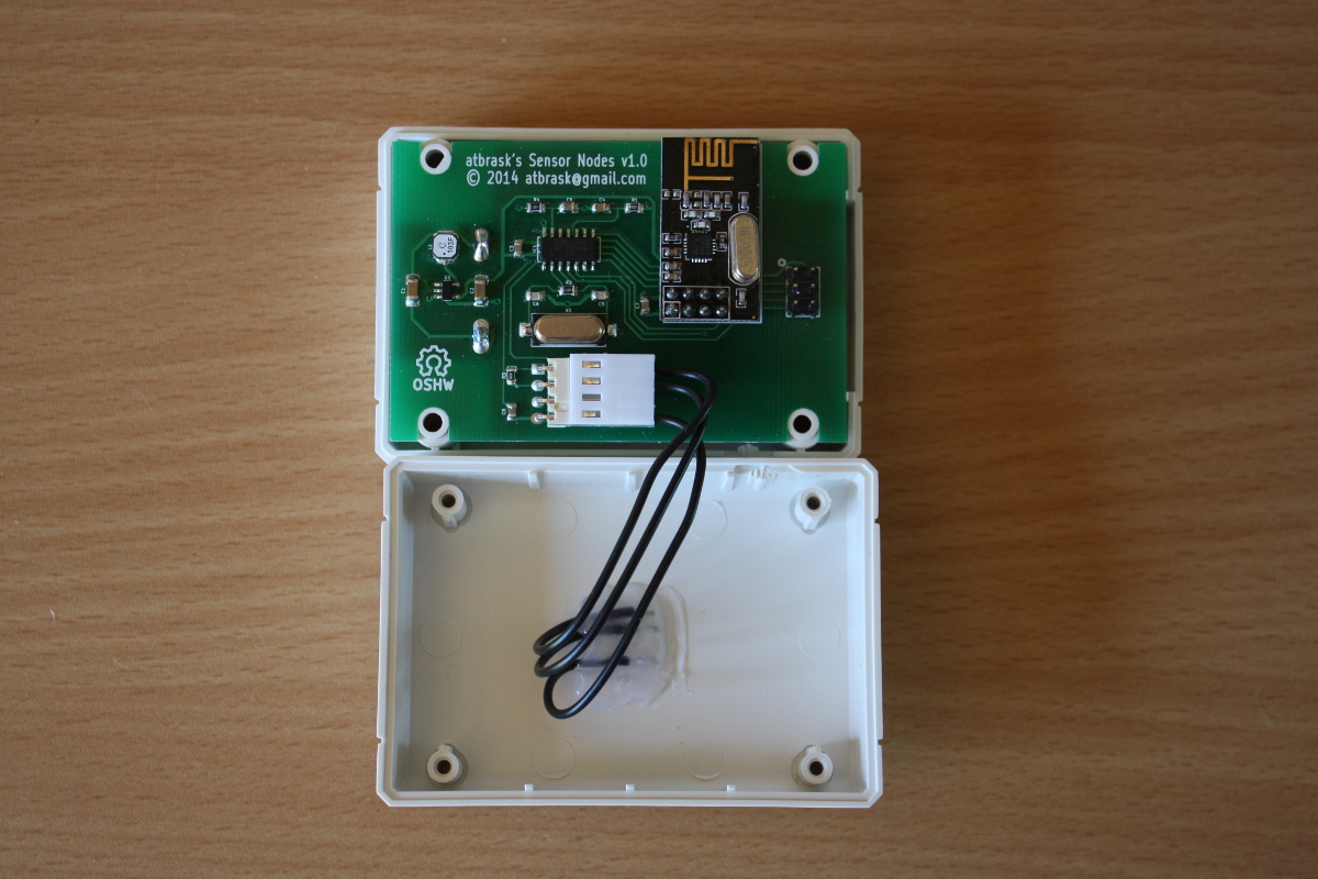
Inside a single sensor node
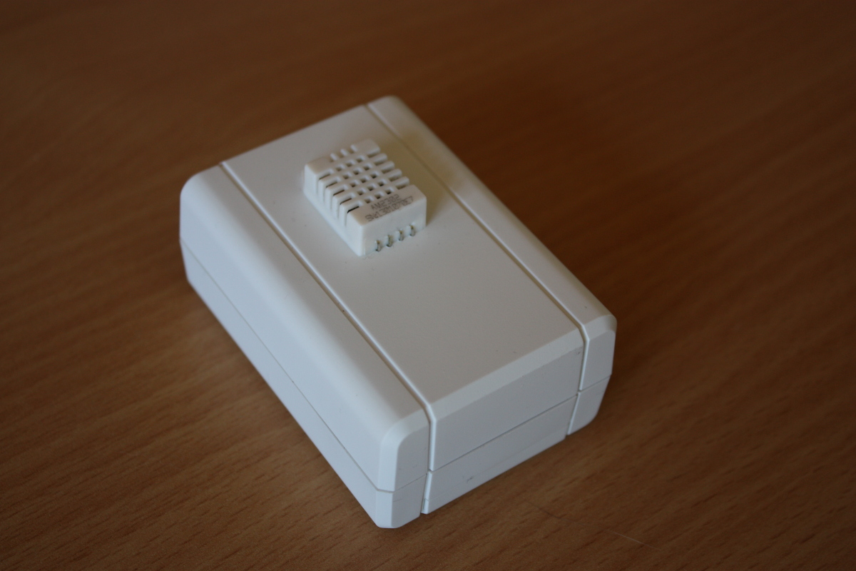
A single sensor node
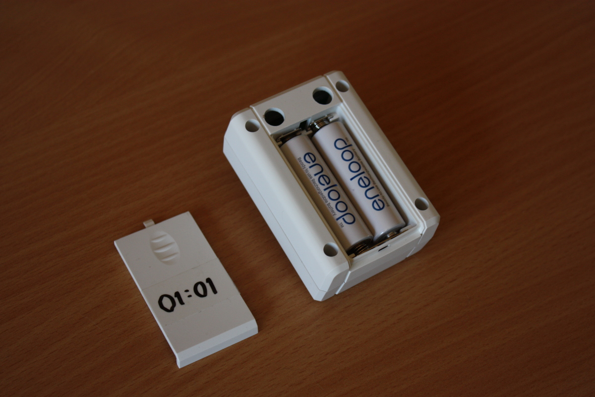
The back of a sensor node
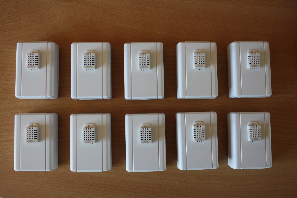
The 10 first sensor nodes
In addition to the DHT22 sensors, I have also made firmware for collecting data from a wind vane and a rain gauge. But I haven’t deployed any of that yet. Maybe next spring…
All in all the main results for the sensors are:
- They work! I have tested concurrent operation of 10 units without major problems.
- Firmware optimized for ATtiny84 @ 1 MHz (8MHz crystal with the CKDV8 fuse set)
- Temperature and humidity measurement using a DHT22 sensor
- Wind speed and wind direction measurement using a La Crosse TX23 anemometer
- Rainfall measurement using a WS-2300-16 rain gauge
- Wireless operation using the very popular nRF24L01+ 2.4 GHz radio chip
- Very compact CRC32 implementation
- Battery powered operation using a very efficient 3.3v DC/DC converter
- Power management by sleeping the CPU and turning off unneeded hardware
- Battery voltage measurement included in data packet
- Typical battery draw while sleeping has been measured to around 17uA
- Total firmware size from 3.0 kiB to 3.5 kiB (depending on sensor type)
The base station
I use a Raspberry Pi as base station. To make it more appliance-like than a typical Raspbian installation, I have instead installed a variant of Tiny Core Linux called piCore. This is basically a very small Linux distribution that loads all programs into memory on boot and leaves the SD card alone after this. This eliminates the usual risk of corrupting the file system when doing a power-cycle.
On the base station I have installed a small python script that continually polls the nRF24L01 radio using the Raspberry Pi’s built-in SPI interface pins. When a data packet arrives, it is buffered (in case of network problems) and forwarded to the database.
The database
With my limited data requirements, I could probably use any old database out there without issues. However, given the nature of the data, it was natural to select a so-called timeseries database. For this project I chose InfluxDB, which was very, very easy to set up on my Ubuntu-based file server. It automatically exposes a simple HTTP interface for storing and querying data, which is just what I need for this project.
The frontend(s)
Well, I’m not quite there yet… So far the only frontend is the admin interface that is built in to InfluxDB. Not very user friendly (not to mention the Wife Acceptance Factor)! The next step now is to make some sort of nice frontend for this. I have several ideas floating around my head:
- An intranet website. The easiest way.
- An Android widget. Both the wife and I have Android smartphones.
- Dedicated hardware devices. This would be a great use-case for my new ESP8266 wifi modules and some 84×48 Nokia LCDs I have lying around.
Stay tuned…
21 Comments
Thomas COUTANCEAU · 2015-01-14 at 12:10
Hello,
I want to make a weather station (anenometer) with raspberry pi and the TX23.
Could you put some info about this? How to connect the TX23 to the PI, how to collect the data?
Thanks.
atbrask · 2015-01-14 at 20:15
Hi,
I have implemented some code that can sample the TX23 anemometer from one of the wireless sensor nodes in my system. You can find the code in my GitHub repository for this project. There is a link in this blog entry near the top. It is just regular C++, but in its current state it’s only running on Atmel AVR microcontrollers. I should be possible to port to the Raspberry Pi using a single GPIO pin. Another option would be to flash it onto e.g. an ATtiny85 and connect to that from the Pi. That would off-load some timing critical code from the Pi.
Regarding the data protocol of the TX23 I used these links:
https://www.john.geek.nz/2012/08/la-crosse-tx23u-anemometer-communication-protocol/
http://www.rd-1000.com/chpm78/lacrosse/Lacrosse_TX23_protocol.html
http://www.rd-1000.com/chpm78/lacrosse/Receive_Lacrosse_TX23_data_2.html
Bogdan · 2015-01-17 at 15:36
Congrats for the project!
I am thinking of something similar but with OpenHab integration.
1. Do you get good range with the NRF modules?
2. What is the expected battery life for each sensor?
3. Have you considered storing a DB locally on the RPi gateway?
4. Do you get low battery alert/notification (somehow) for each sensor?
atbrask · 2015-01-17 at 16:44
Thanks 🙂
OpenHAB integration would a cool addition! As for your questions:
1. Inside the house I have almost perfect reception from the sensors. It’s sometimes a bit spotty for the outside sensors. Every data packet contains an increasing sequence number which makes data quality issues easy to detect. I think the range is comparable to our regular wifi network.
2. I have absolutely no idea… 🙂 I hope they’ll last a year on each charge. They have been running a couple of months now, and so far my data only shows a tiny dip in voltage. The voltage itself probably isn’t a great indicator of battery health, but it’s very easy to measure. Each sensor contains 2 eneloop AA batteries, and the mean voltage right now is around 2.6 volts. 2000mAh goes a long way when the current in sleep mode is measured in the lower two-digit uA.
3. Yes, but I decided to keep the RPi as “idiot proof” as possible so a power failure or a SD card failure wouldn’t corrupt anything. Essentially it’s only a data gateway, but it does buffer the data if the database server becomes unavailable for a while.
4. Well, yes and no. One of the ATtiny’s analog inputs is used as a simple voltmeter for the battery. I collect and store everything, but I haven’t (yet) set up any alert system.
Alan Medina · 2015-07-30 at 06:15
Hi! congrats for your project!! its amazing… i have a question… how can i measurement the battery voltage using a 3.3v DC/DC converter?, in my case i use de NCP1402. I see that in your schematic you use a 1M resistor and 100nf capacitor, Can you give me a explanation?
regards 😀 … sorry for my bad english
atbrask · 2015-07-30 at 07:38
Thank you! 🙂
The Attiny MCU runs on a more or less steady 3.3v from the DC/DC boost converter regardless of the actual battery voltage. The batteries are then also connected directly to an analog input through a 1M resistor and 100nf capacitor (which you noticed) that act as a low-pass filter. I don’t really know if it’s necessary, though..
However, the point is that this analog input can be used as a voltmeter in the range 0v…3.3v. It works because the battery voltage in this case by definition is less than 3.3v. The A/D converters in AVR MCUs have 10 bits of resolution, which gives us a reading in the range 0..1023. Here 0 means 0v and 1023 means 3.3v. I assume that it’s fairly linear across the entire range, but I don’t know if that’s true. So if it reads e.g. 806 then the batteries are at 2.6v.
I have no reason to believe that it won’t work with the NCP1402. As long as it outputs a reasonably clean 3.3v there should be no problem.
And by the way.. Your English is fine. 🙂
Alan Medina · 2015-07-30 at 23:49
ok, thanks for your help, I’ll try and see what happens … 😉
regards
Kris · 2015-10-12 at 23:30
Hey Asbjørn… Great project! I’m trying to compile under Windows (win-avr) but getting loads of errors… Do you happen to know what version of avr-libc is required ?
src/SensorNodeTypes.h:25: error: use of enum ‘SensorTypeEnum’ without previous declaration
src/SensorNodeTypes.h:25: error: expected unqualified-id before ‘:’ token
src/SensorNodeTypes.h:36: error: use of enum ‘QualityEnum’ without previous declaration
src/SensorNodeTypes.h:36: error: expected unqualified-id before ‘:’ token
src/SensorNodeTypes.h:62: error: ‘SensorTypeEnum’ does not name a type
src/SensorNodeTypes.h:63: error: ‘QualityEnum’ does not name a type
atbrask · 2015-10-13 at 07:17
Hi,
Thanks! It’s still a work-in-progress project, but at least the sensors have now been running for close to a year on their first charge without hiccups.
As for your problem I don’t think the specific version of avr-libc is the problem. I’m almost completely sure it’s caused by missing compiler flags. You’ll need to compile using the bundled Makefile or alternatively copy all the compiler flags from it into your build setup.
The errors you pasted in here relate to the declaration of some of the enumerations. They are declared with an underlying type to specify explicitly how they are to be serialized when the data is transmitted. I don’t use win-avr, but as far as I know it uses gcc as its compiler, and in gcc it’s a fairly new feature, so you need the compiler flag -std=c++0x
I have only tested that the project can compile from the command line on Linux and OS X. If you still experience problems, I can try installing win-avr on my Windows box.
Kris · 2015-10-13 at 09:48
Hey Asbjørn
Thanks for the quick response … I was also under the impression this may be due to the win-avr on Windows, but last night I tried building it under linux(ubuntu), and the results are the same… I’m using the make file you’ve supplied, and the flag is there. I’ve installed avr-libc via the package manager, so not sure if it’s up to date … any chance you can check the version of avr-libc you’re using ?
I’m really keen to get this going, I’m redesigning the PCB to fit a more conventional sensor case, and I will use it to manage central heating in my house … time is of the essence, winter is coming 😉
:~/Node/RPIWeather/SensorNodes/Firmware$ make rebuild UNITID=0x0102 VCC=3320 SENSORTYPE=DHT22
rm -f bin/*
avr-gcc -Os -fdata-sections -ffunction-sections -Wl,–gc-sections -Wall -mcall-prologues -mrelax -mmcu=attiny84 -std=c++0x -DF_CPU=1000000 -DVCC=3320 -DUNITID=0x0102 -DSENSORTYPE=DHT22 -DFIRMWAREVERSION=0x0104 -DMAGICNUMBER=0x20130928 -DTXPIPE=0x2013092801LL -DRXPIPE=0x2013092802LL -DCHANNEL=0x5c src/Battery.cpp src/CRC32.cpp src/DHT22.cpp src/PowerManagedSensor.cpp src/Sensor.cpp src/SensorNodeMain.cpp src/TX23.cpp src/WDTSleep.cpp src/WS_2300_16.cpp -o bin/firmware.obj
src/CRC32.cpp:22: warning: only initialized variables can be placed into program memory area
In file included from src/Sensor.h:25,
from src/PowerManagedSensor.h:22,
from src/DHT22.h:22,
from src/DHT22.cpp:23:
src/SensorNodeTypes.h:25: error: use of enum âSensorTypeEnumâ without previous declaration
src/SensorNodeTypes.h:25: error: expected unqualified-id before â:â token
src/SensorNodeTypes.h:36: error: use of enum âQualityEnumâ without previous declaration
src/SensorNodeTypes.h:36: error: expected unqualified-id before â:â token
src/SensorNodeTypes.h:62: error: âSensorTypeEnumâ does not name a type
src/SensorNodeTypes.h:63: error: âQualityEnumâ does not name a type
src/SensorNodeTypes.h:64: error: ISO C++ forbids initialization of member âValueâ
src/SensorNodeTypes.h:64: error: making âValueâ static
src/SensorNodeTypes.h:64: error: ISO C++ forbids in-class initialization of non-const static member âValueâ
src/SensorNodeTypes.h:70: error: ISO C++ forbids initialization of member âMagicNumberâ
src/SensorNodeTypes.h:70: error: making âMagicNumberâ static
src/SensorNodeTypes.h:70: error: ISO C++ forbids in-class initialization of non-const static member âMagicNumberâ
src/SensorNodeTypes.h:71: error: ISO C++ forbids initialization of member âFirmwareVersionâ
src/SensorNodeTypes.h:71: error: making âFirmwareVersionâ static
src/SensorNodeTypes.h:71: error: ISO C++ forbids in-class initialization of non-const static member âFirmwareVersionâ
src/SensorNodeTypes.h:72: error: ISO C++ forbids initialization of member âUnitIDâ
src/SensorNodeTypes.h:72: error: making âUnitIDâ static
src/SensorNodeTypes.h:72: error: ISO C++ forbids in-class initialization of non-const static member âUnitIDâ
atbrask · 2015-10-13 at 10:09
Hmm.. That’s a bit weird as I did most of the development on my Ubuntu box. I’ll take a look at this tonight. Which version of Ubuntu are you using?
Cool project you have there! I don’t control anything in my setup. It’s purely for monitoring and self-education. Are you planning to implement your own data collection backend and frontend like I’m doing (slowly) or are you going to use one of the cloud based options like, for example, ThingSpeak?
Pro tip: If you are ever going to put a sensor outside, then I suggest finding another sensor than the DHT22. It really, really doesn’t like dew. During the past year I have destroyed two of them by simply putting them outside. My current one measures temperature OK, but the relative humidity reads as 1%. Somehow I doubt that…
Winter is indeed coming! The night is dark and full of terrors. 😉
Kris · 2015-10-13 at 13:20
Solved, used a new Ubuntu installation (14.04) and it just worked no problem. Looks like win-avr is a no go, but on updated linux platform the compile works fine.
Thanks for the “pro tip”, all of my nodes are intended to be installed inside the house so should be good with the DHT22 …
Now I need to figure out how to get RTC working with piCore as I can’t always rely on NTP 🙂
atbrask · 2015-10-13 at 16:59
I just had a look at WinAVR. The latest version I could find is from 2010 and includes GCC 4.3.3, which is incompatible with the C++ code in this project. As far as I can deduce, the typed enum stuff I talked about earlier wasn’t added until GCC 4.4.
As for piCore, you could just as well use Raspbian. I just like piCore because it’s so lightweight and simple. That is, until you realise that you need to create your own packages for everything slightly less common… 🙂
Søren Jensen-Sondrup · 2018-01-09 at 09:29
Hej Asbjørn
See that you use a ESP8266 together with a tiny in your project – suggest have a look at this:
https://github.com/palsbo/Autopilot-for-XPlane-with-ESP8266
The 8266 can easily handle all your processing needs, including reading the DHT22 (which by the way are not very good for humidity – very much spreading between devices, temps are fine though.) It also works well in deep sleep mode. For operation with 433MHz receiver I suggest the ESP07 (I think it is called) which has a shield over the processor, and also more I/O pins available.
Just skimming your code as I need to decode a OBH device on 433.
Hilsen Søren
PS: Har du aner på Kjellerup Gods syd for Hobro?
atbrask · 2018-01-09 at 10:13
Hej Søren,
Lad os bare tage den på dansk her. Så må resten af verden bruge Google Translate, hvis de vil kigge med. 🙂
ESP8266 er ganske rigtigt en meget kapabel processor, der snildt ville kunne lave alt benarbejdet i projektet. Jeg bruger dog en attiny84 i måleenhederne, da den bruger meget lidt strøm i sleep mode. Desuden kom ESP8266 først frem kort tid efter jeg var færdig med at lave enhederne. Det der i billederne ligner en ESP-01 er en nRF24L01 (modul til 2,4GHz datatransmission, men protokollen er tættere på BLE end Wifi – og de bruger meget lidt strøm). Systemet har nu kørt i over 3 år uden opladning af batterierne og uden at spændingen over dem er faldet nævneværdigt. Hver boks har 2x NiMH AA Eneloop batterier og generelt er spændingen på de 3 år gået fra omkring 2,65 volt til 2,55 volt. Der kan ESP8266 ikke helt være med. Man kan godt få den til at gå i deep sleep mode, men under wifi-transmissioner bruger den temmelig meget strøm.
Jeg har dog flere gange leget med at bruge ESP8266 (og den nyere ESP-32) til at drive trådløse displays til projektet. For tiden leger jeg lidt med et ESP-32-modul med indbygget OLED-display. Men det kniber lidt med tiden til at gøre det færdigt…
Angående DHT22 er det også min erfaring at det er så som så med nøjagtigheden. Især tåler de ikke at sidde udendørs ret længe før fugtighedsmålingen fryser fast på f.eks. 99%. Jeg har prøvet med en HTU21D i stedet, men den har lignende problemer. Kan du anbefale andre sensorer? Jeg har en BME280 liggende, som jeg vil prøve med, men er bange for at det bliver samme resultat.
Mvh Asbjørn
PS: Der er så vidt jeg ved flere Brask-slægter, hvor en af dem ganske rigtigt har med godset der at gøre. Men min fars familie er fra Sjælland, så jeg ved ikke om der er en forbindelse.
Søren Jensen-Sondrup · 2018-01-09 at 16:02
Hej Asbjørn
Wow, det var imponerende batteritid. Det kan 8266 ikke klare. Jeg har nogle sensorer med 8266 og DHT22, og der er batteritiden ca. 6 måneder. 22’eren kører konstant, da den er meget længe om at komme i omdrejninger, hi. Jeg bruget et lithium 18x65mm 4,7V batteri, husker ikke data, men det er en kineservare. Jeg starter den op hvert tiende minut og sender data til en server via UDP.
Jeg har desværre ikke et godt bud på en troværdig fugtighedssensor, men det ser ud til at de OBH’er jeg har er rimeligt enige – måske skal de dissikeres, så man kan se hvad de bruger?
Angående slægt, så havde jeg kontakt med en dame fra Helsingør for nogle år siden angående Brask, og fik bl.a. nogle billeder. Du kan se dem hvis du kigger her:
http://158.248.209.233:84/webtrees
og søger på brask.
Jeg husker ikke, hvor mange led tilbage hun skulle før slægten var på Sjælland, men måske er vi en ganske lille bitte smule i familie….
mvh Søren
atbrask · 2018-01-10 at 13:42
Hej igen,
Ja, jeg er også svært tilfreds med levetiden. En af finterne er at de her Eneloop batterier har meget lav selvafladningsstrøm, så de holder på en opladning meget længe. Det er en stor fordel når man bruger så lidt. 6 måneder er skam også meget fint for en 8266 på en lithiumcelle!
Du skriver at DHT22 er lang tid om at komme i omdrejninger. Tænker du her på at selve målingen tager lang tid eller har du observeret at de skal være tændt et stykke tid før målingen er præcis/stabil? Jeg “snyder” lidt ved at strømføde DHT22’en fra et IO-ben på attinyen, så jeg kan slukke den når jeg ikke bruger den. En gang hvert 5. minut tænder jeg den, venter ca 8 sekunder, tager en måling og slukker igen. Jeg har ikke brugt så meget krudt på at undersøge, om det ødelægger målingen at tænde og slukke for sensoren. Men det kunne være interessant at høre andres erfaringer.
Mht slægt har jeg desværre ikke styr på det så langt tilbage i tiden.. Jeg kan prøve at spørge min storebror der er familiens “arkivar”. 🙂
Asbjørn
Søren Jensen-Sondrup · 2018-01-10 at 15:55
Hej Asbjørn
Jeg kan dårligt huske detaljerne, men jeg brugte ganske meget tid på at få DHT22erne til at makke ret og lykkedes ikke helt. Jeg lavede vist også nogle ændringer i library filerne for at kunne læse dem hurtigere. Det er over et år siden, så detaljerne er lidt slørede… Jeg har dog planlagt at tage dem op igen for at forsøge at forbedre dem. En ting der lige slår mig er at jeg altid har brugt en uskærmet 8266, måske er der HF-indslag, der forstyrrer DHT22erne – nu hvor jeg roder med 433, kan jeg se at den uskærmede 8266 støjer meget, så måske er det noget af forklaringen. Jeg kører også på 3.3V og det er jo bundgrænsen for DHT22, så måske en kombination af mindre støj og mere spænding kan forbedre situationen. Jeg skal lade dig vide når jeg har forsøgt en anden opstilling.
Din løsning med at strømføde via en port er smart, men der ligger du nok også lige i underkanten af de 3.3V til DHT22erne.
Bruger du library eller har du selv lavet kommunikation til 22erne?
Jeg forsøgte lige at skille OBH sensoren ad, men de har valgt nogle meget små skruer, der er forsænket i materialet, så ingen af mine mange bittesmå skruetrækkere kan klare jobbet – træerne skulle jo nødeg vokse ind i himlen, hi.
mvh Søren
Emilio Pastore, Jr · 2018-03-19 at 06:17
Hi !
Congratulations for such an in depth project sharing, very nice indeed. Would you be interested in exporting some complete units like these ones ?
Great job !
– Emilio
atbrask · 2018-03-19 at 09:16
Hi,
Thanks!
I’m afraid you’re on your own. I only have few spare parts left for my own running system. But I guess it would be pretty easy to source all the parts from Mouser. The usual PCB houses in China should also be able to make you a set of boards using the Gerber files in the project’s GitHub repository.
/Asbjørn
RPIWeather: Adding off-the-shelf wireless sensors | The ramblings of atbrask · 2016-04-16 at 20:44
[…] I have been developing and using my own home-built wireless thermometer/hygrometer system called RPIWeather (which is open source). Then the other day I discovered that the previous owners of our house (my […]